HNC PLC User Manual. HC Series Card-type PLC
Contents
Communication Expansion Module AE-1C User Manual
1. Product model list and dimension
3
2. Indicator description
3
3. Environmental specification for product
3
4. Module terminal wiring diagram
3
5. AE-1C wiring diagram (RS485&RS232)
4
6. Module connection method
4
Communication Expansion Module AE-1C Application Example
1. Module power supply
5
2. Applicable MPU
5
3. Hardware configuration and communication port number
5
4. Communication protocol
5
5. PLCbus communication example description:
6
5.1 Communication between two HNC MPUs
6
5.2 Example of a disconnection alarm program for slave communication
8
6. Modbus communication example introduction:
8
6.1 Communicate with TE-8RC thermal resistance IO communication module
8
6.2 Read and Write the inverter frequency example
8
7. Typical free protocol applications:
9
7.1 Tn=0,Rn>0,only receive data
9
7.2 Tn>0,Rn=0,only send data
11
7.3 Tn>0,Rn>0,for example, communication with YUDIAN instruments by AIBUS
11
8. The system registers of communication timeout time, communication instruction execution interval, communication port
character receiving timeout time and application introduction
13
9. When PLC is used as slave station, there is no need to to write any communication program, and supporting a variety of HMIs
and configuration softwares
15
10. How to judge the communication failure and program analysis when PLC is used as slave
17
11. Check-code calculator usage introduction
17
12. The introduction of supportive baud rate, data format and communication instructions when PLC communication port is used
as a master/slave station
18
12.1
PLC communication port used as a master station:
18
Supported by AC, AT, AH series MPU communication port:
18
12.2 PLC communication port used as a slave station:
18
13. PLC communication common problems
19
2 / 19
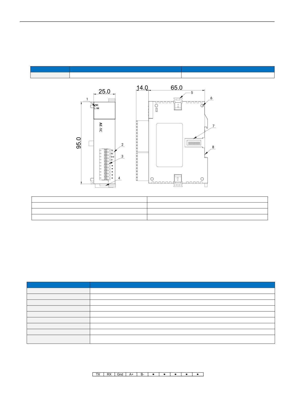
Communication Expansion Module AE-1C User Manual
1. Product model list and dimension
Models
Power Consumption(24VDC)
Dimension(W × H × D)
AE-1C
DC24V~0.1A MAX
25×95×65 mm
1. PWR power indicator, LINK module communication indicator
5. Module connection buckle
2. Terminal definition
6. Module positioning hole
3. Removable terminal
7. Module expansion port
4. Track Buckle
8. 35mm DIN guide rail
2. Indicator description
z PWR:power indicator. green, constant light - Power normal; Not light - Power abnormal.
z LINK:indicator constant lighting - MPU has identified the module;indicator Green jitter - Module is communicating with MPU.
Red jitter quickly - Firmware not completed.
3. Environmental specification for product
Items
Environment Specifications
Temperature/Humidity
Operating temperature:0~+55℃ Storage temperature:-25~+70℃ Humidity: 5~95%RH, No condensation
Vibration Resistance
10~57 HZ, amplitude=0.075mm, 57HZ~150HZ acceleration=1G, 10 times each for X-axis, Y-axis and Z-axis
Impact Resistance
15G, duration=11ms, 6 times each for X-axis, Y-axis and Z-axis
Interference Immunity
DC EFT: ±2500V
Landing
Third earthing (not common to high voltage systems)
Over Voltage Resistance
1500V AC/1min between AC terminal and PE terminal, 500VAC/1min between DC terminal and PE terminal
Insulation Impedance
Between AC terminal and PE terminal @500VDC,>=5MΩ ,all input/output points to PE terminal @500VDC
Operating environment
Avoid dust, moisture, corrosion, electric shock and external shocks
No isolation between channels, use optoelectronic isolation for the communication interface and the internal
Isolation mode
power supply
4. Module terminal wiring diagram
AE-1C Module
3 / 19
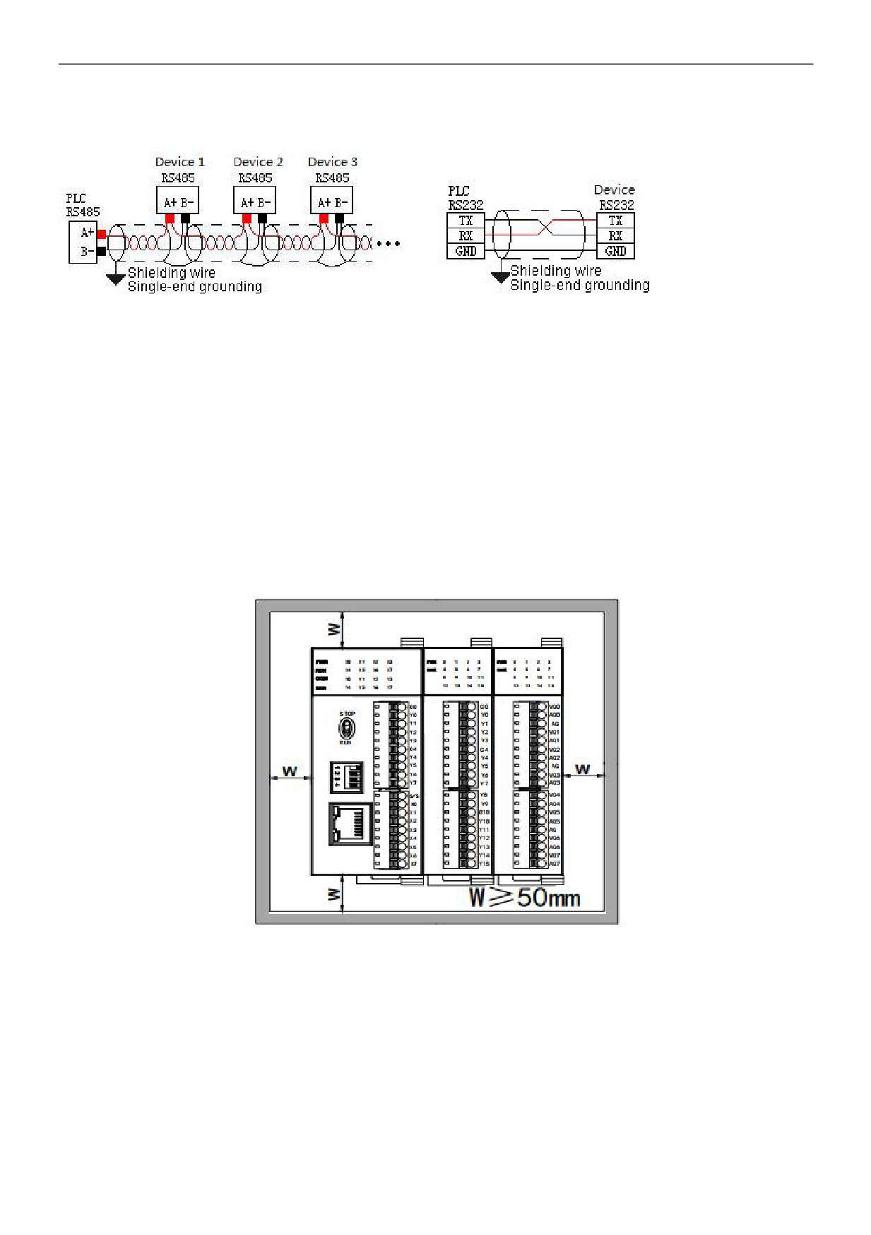
5. AE-1C wiring diagram (RS485&RS232)
6. Module connection method
The PLC should be secured to an enclosed cabinet while mounting. For heat dissipation, make sure to provide a minimum
clearance of 50mm between the unit and all sides of the cabinet. (See the figure.)
Rail Mounting: Use standard 35 mm rail.
Connecting Extended Module
Join lower right parallel interface of Last module (MPU or Extension Module ) to the lower right of the parallel interface of next module, then
tight with two buckles on top and bottom.
The interface of the right side module is left for extension interface for next extension module.
4 / 19
Communication Expansion Module AE-1C Application Example
1. Module power supply
Module is directly hung behind the MPU and powered by parallel port, no need to take external power supply.
2. Applicable MPU
HCG, HCM series PLC can be expanded with communication modules, the maximum can be expanded with 3 AE-1C modules.
3. Hardware configuration and communication port number
MPU is built-in 2 communication ports, respectively are ethernet port and COM2 for RS485 port; the A + B- terminal on terminal
row. Communication expansion module AE-1C not only can be used as RS232, but also can be used as 485 , no program
definition required. It depends on the external wiring, AE-1C can be used as RS485 when connected to RS485 port or it can be
used as RS232 when connected to RS232 port, but it only can choose one or the other one.
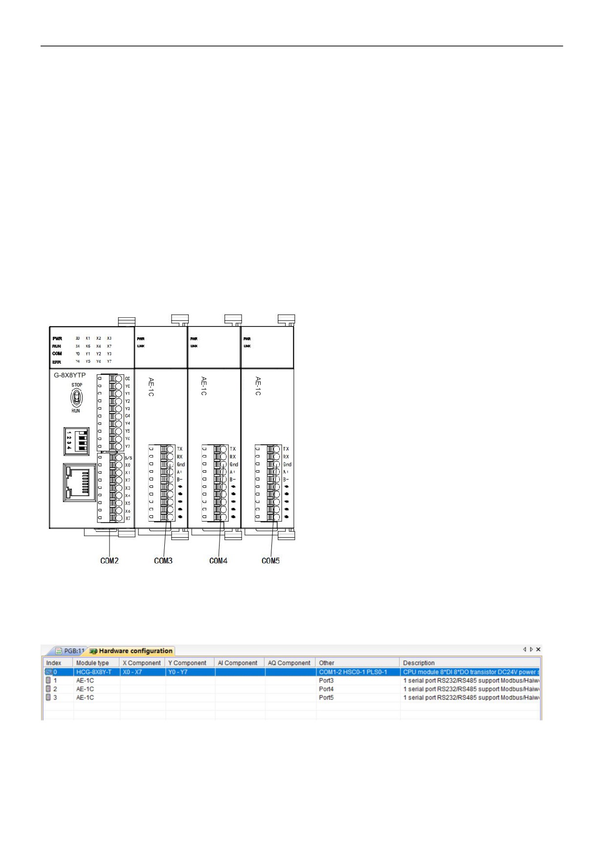
When the communication module is expanded, the communication port closest to the MPU is COM3, next is COM4 and last is
COM5. The position of communication module can be random, and the communication port number can be viewed in the
hardware configuration, as shown in the figure below:
4. Communication protocol
It is built-in Modbus RTU / ASCII protocol, freedom communication protocol and PLCbus high-speed communication protocol of
HNC company (each port supports all the above protocols). One communication port can take different baud rates, different data
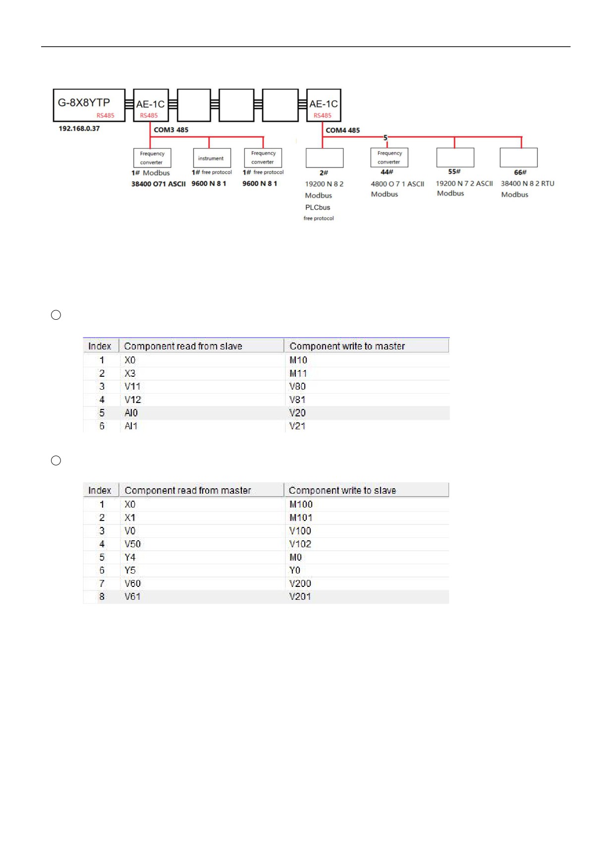
formats, different communication protocols at the same time, as you can see in the following network diagram, two RS485
networks can be normal and efficient communication.
5 / 19
5. PLCbus communication example description:
5.1 Communication between two HNC MPUs
This example shows the communication between two MPUs. It is known that communication baud rate is 19200 between the
master and slave PLC, data format is N 8 2 RTU, and slave station number is 2.
1
Master reads 2 # slave data: for example, read X0 of slave into master M0; read X3 of slave into master M11, etc., as
follows:
2
Master writes 2 # slave data: for example, write V0 of master into slave V100; write V50 of master into slave V102, etc., as
follows:
Programming ideas:
In the HNC PLC programming software, set up PLCbus read communication table, special floating-point and 32-bit data occupy
two consecutive addresses, if the master wants to write the floating-point or 32-bit data into the slave, it needs to fill two
consecutive registers, such as write V11V12 into V80 V81, as follows:
6 / 19
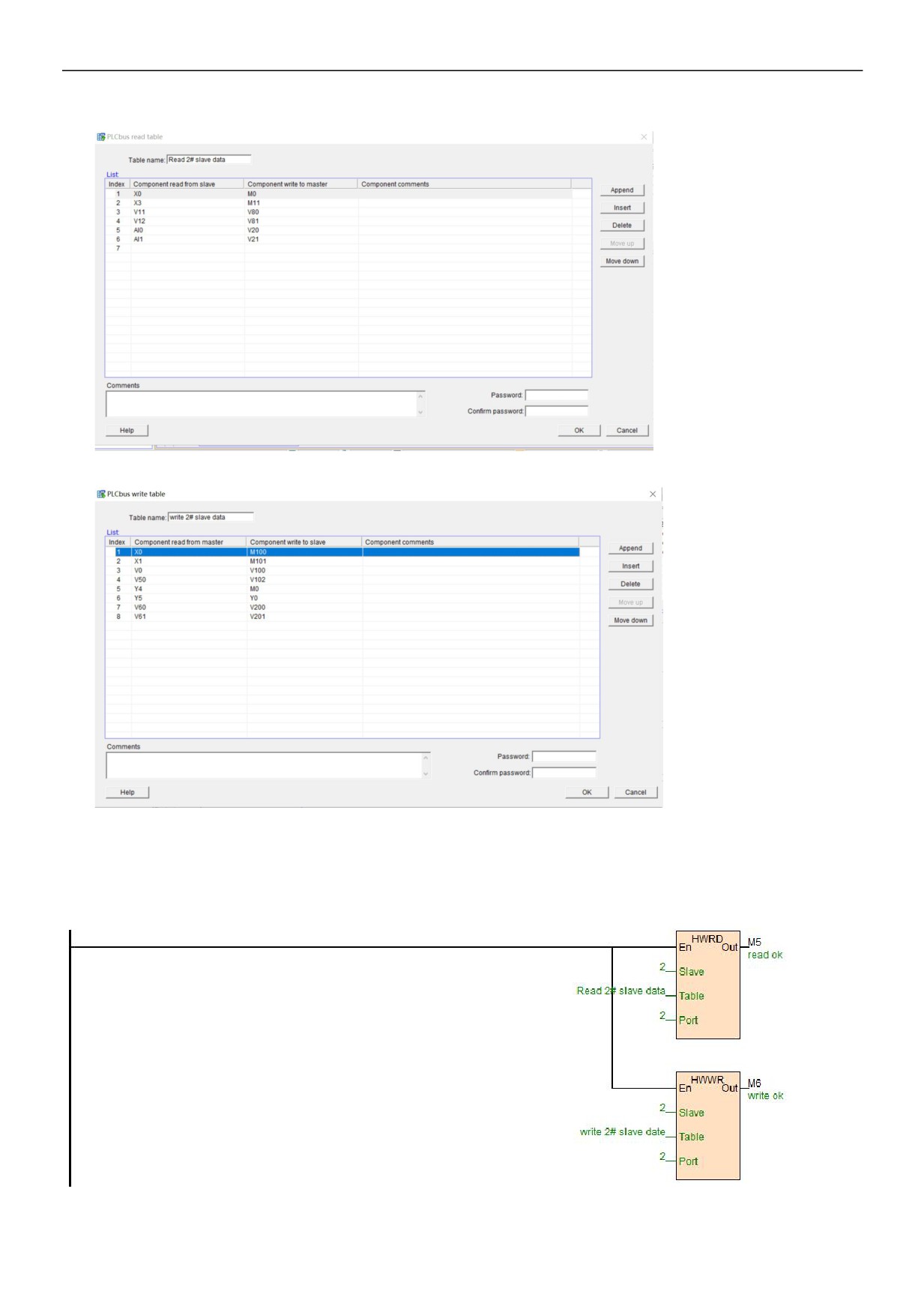
In the HNC PLC programming software, set up PLCbus write communication table, as follows:
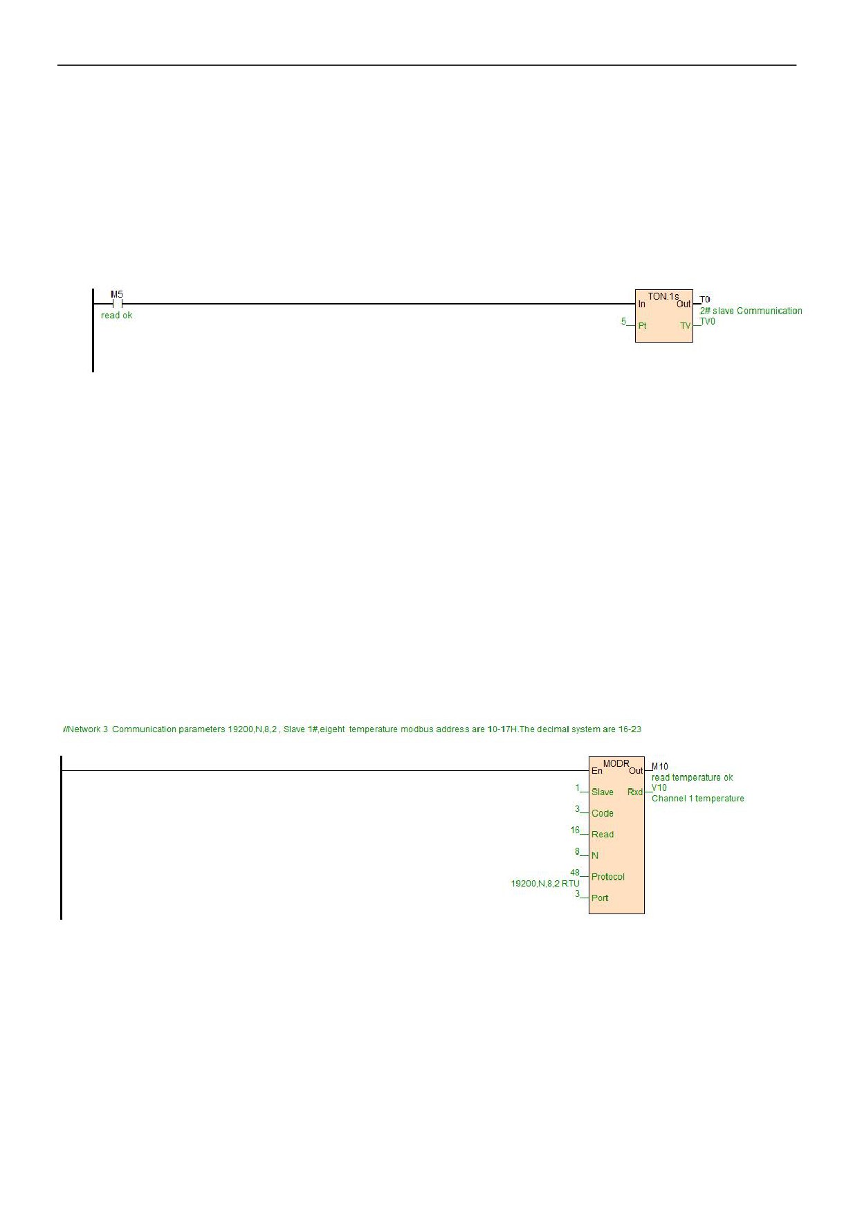
After the table is established, use HWRD and HWWR instructions, and enter the slave address in the "Slave" terminal of the
instructions. In this case, the slave PLC address is "2", directly input the table name in the "Table", or double-click the terminal to
select the established table. "Port "is the communication port number, as described in the second point above, "2" indicates the
master's COM2 for 485 communication port. In this way, the communication program which reads and writes from the slave is
completed, as follows:
7 / 19
5.2 Example of a disconnection alarm program for slave communication
Judging the communication error code situation through the communication instruction "Out" terminal. "Out" terminal has power
indicating that communication is very good without error; "Out" terminal has no power indicating that the communication does not
succeed, in this way, just check the slave parameter settings and networking wiring; "Out" terminal flashes to indicate a
communication error code, and occasional error code in communications does not matter, communication may be disturbed,
therefore, it is possible to check whether the outside uses shielded twisted pair or not, also, multiple slaves need to be in the way
of "hand in hand" .
The following is an example of a disconnection alarm program for slave communication:
Communication disconnection time can be set according to the actual, the above when M5 is more than 5 seconds in OFF state,
T0 coil will indicates communication disconnection alarm.
6. Modbus communication example introduction:
In this example, the MPU is expanded with a communication expansion module AE-1C, communication port is 3, the
communication port is connected to a HNC thermal resistance module TE-8RC and a inverter:
6.1 Communicate with TE-8RC thermal resistance IO communication module
TE-8RC module is built-in RS485 port which can be used for remote IO, supporting Modbus RTU / ASCII protocol, communication
parameters is 19200 N 8 2 RTU, station number is 1 #, from the programming software online help - hardware manual - expansion
module parameters, we can see the 8 temperature values are stored in Modbus start address 10 ~ 17H, which is decimal 16 ~ 23.
6.2 Read and Write the inverter frequency example
Inverter, 9600 E 7 1 ASCII, station No. 2 #. It is required to read and write the inverter frequency, from the inverter manual we can
see that the parameter address of the setting frequency is 2001H, decimal 8193, and the parameter address of the operating
frequency is 2103H, decimal 8451. In this way, write the program as follows:
8 / 19
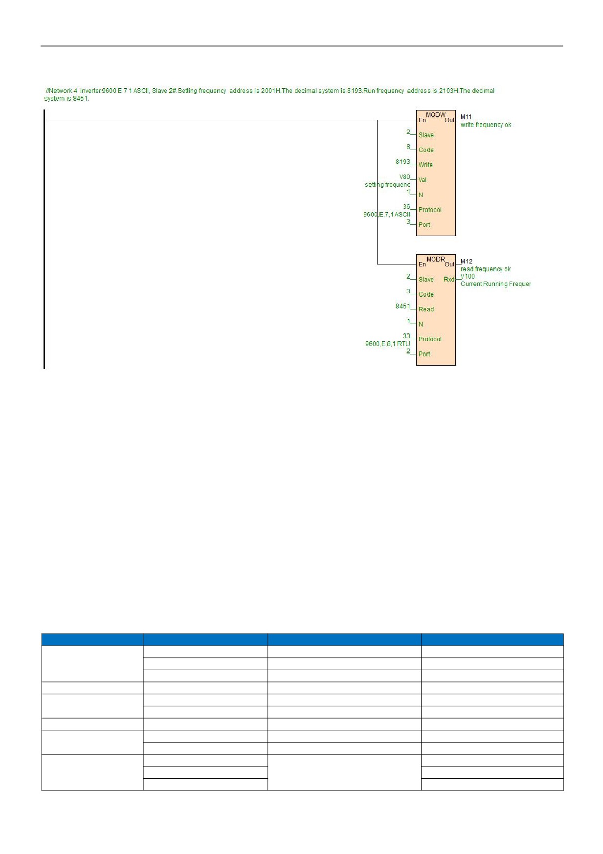
Port = 3, in this example, it indicates the communication port of AE-1C. 8193 can be quickly entered, such as put the mouse on
the "Write" terminal, then it can directly enter 0x2001.
7. Typical free protocol applications:
Serial communication COMM instruction is divided into high-low byte mode and low byte mode. Base on sending and receiving
terms, it can seperate for 3 types: only sending, only receiving and waiting for data receiving after sending commands. For more
detail of instructions introduction, you can refer to the software online help. As for free communication, the essence is to
understand the communication protocol, the following we will introduce the typical application of COMM instruction.
7.1 Tn=0,Rn>0,only receive data
Only receive data, for example, PLC communicates with the weighing instrument, it is known that the weighing instrument has
RS485 port, the baud rate is 9600, data format is E 7 1 ASCII, the weighing instrument generally has two modes, query mode and
continuous sending mode. Continuous sending mode, it indicates that the instrument intermittently send the current weight to the
communication port, so as long as the PLC side is responsible for receiving data.
It is known that the weighing instrument sends 18 bytes of data to the communication port for each time, and the 18 bytes
respectively represent the specific meanings as follows:
Byte order
ASCII symbol
Hexadecimal number
Meaning
OL
4FH 4CH
Overrange
1~2
ST
53H 54H
Static load
US
55H 53H
Dynamic load
3
,
2CH
Separator
NT
4EH 54H
Net weight
4~5
GS
47H 53H
Gross weight
6
,
2CH
Separator
+
2BH
Positive sign
7
-
2DH
Negative sign
0~9
Data
30H-39H
8~14
“”
20H
Space
2EH
Decimal point
9 / 19
Kg
4BH 67H
Kilo
15~16
“T ”
54H 20H
Ton
17
CR
0DH
Enter
18
LF
0AH
Line feed
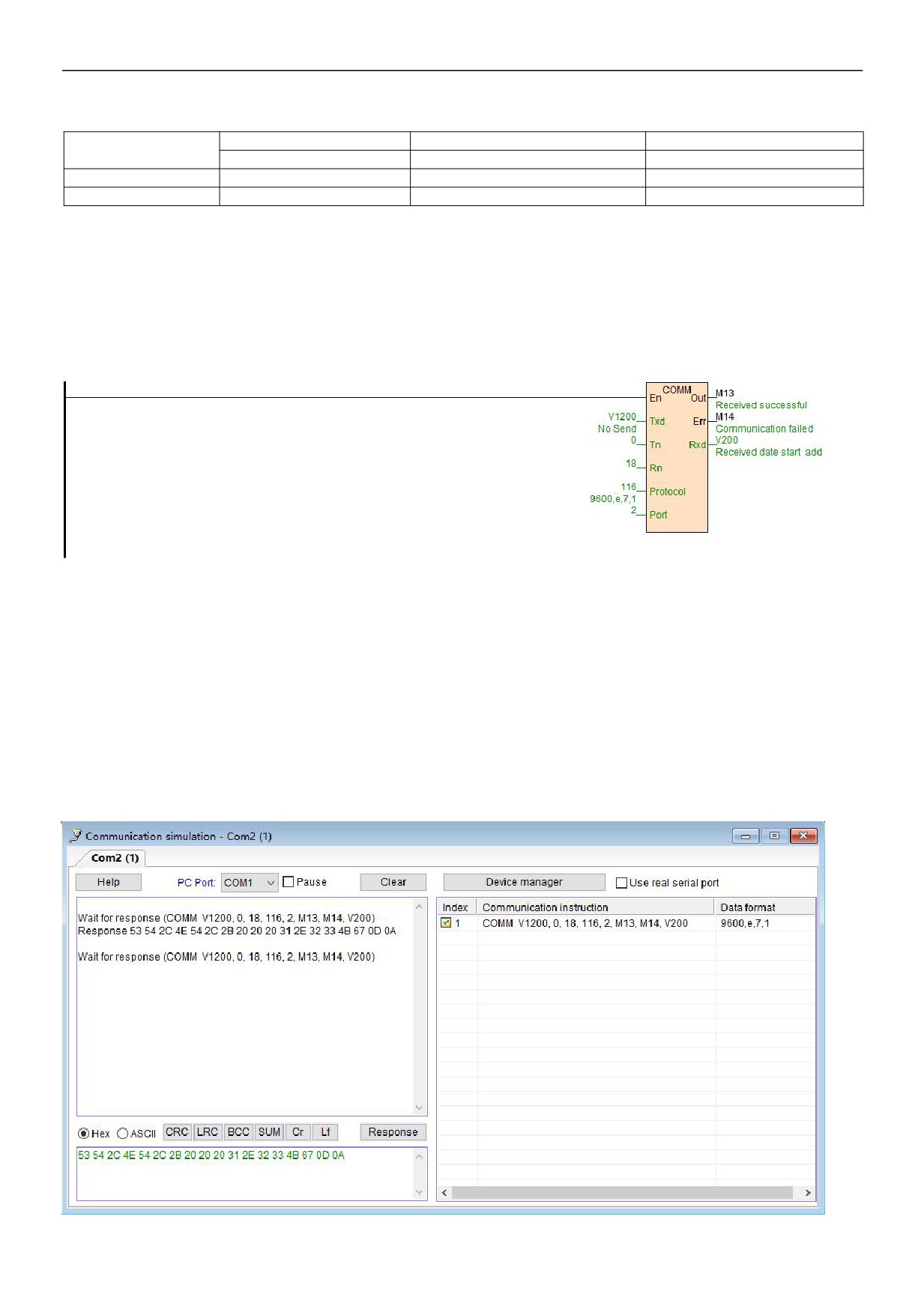
Assuming that the net weight of weighing instrument is 1.23Kg, then the weighing instrument will send 18 bytes of data to the PLC
according to the above format, the data is in hexadecimal:
53 54 2C 4E 54 2C 2B 20 20 20 31 2E 32 33 4B 67 0D 0A
The above data indicating the weight is 2B 20 20 20 31 2E 32 33, it represents 1.23 Kg. 2B is the "+" sign, 20 is a space, 2E is the
decimal point, 30 ~ 39H is the character 0 ~ 9. So we just use the COMM instruction to receive the 18 bytes back, and parse out
the weight we want. In this way, we write the COMM instruction below:
When PLC is running, and COMM instruction is scanned, since Tn = 0, there is no need to send command. Therefore, COMM
instruction will be in receiving status according to baud rate and data format defined by protocol, at this moment, when the
weighing instrument sends the data of 53 54 2C 4E 54 2C 2B 20 20 20 31 2E 32 33 4B 67 0D 0A, the COMM instruction will
receive the data, and store it in the start register of V200, when the data is stored, first stored in the low byte of the register, then
stored the high byte of the register, as follows:
0A0D
674B
3332
2E31
2020
202B
2C54
4E2C
5453
V208
V207
V206
V205
V204
V203
V202
V201
V200
From the above we can see that we want the data in V203 ~ 206, these four registers, a total of 8 bytes. The next is data analysis,
HNC has a very convenient instruction of character to floating point, that is, CTOF. So we write the program as follows, and get the
simulation results through communication simulator running:
10 / 19
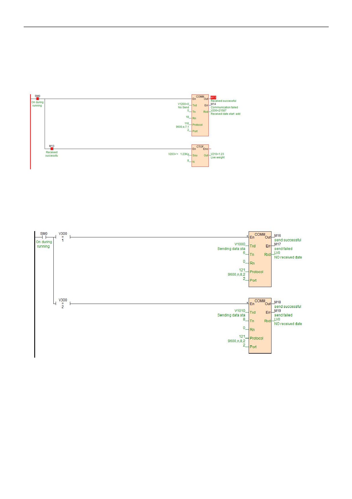
Click on the "simulation", open the communication simulation in the debug menu, fill in the data in the answering area, click on the
"answer" to simulate the communication program, if the serial interface of computer is actually connected to instrumentation, you
can check the "use the actual serial port" so that the software can co-simulation with the actual instrument, very convenient. The
final simulation program is as follows:
7.2 Tn>0,Rn=0,only send data
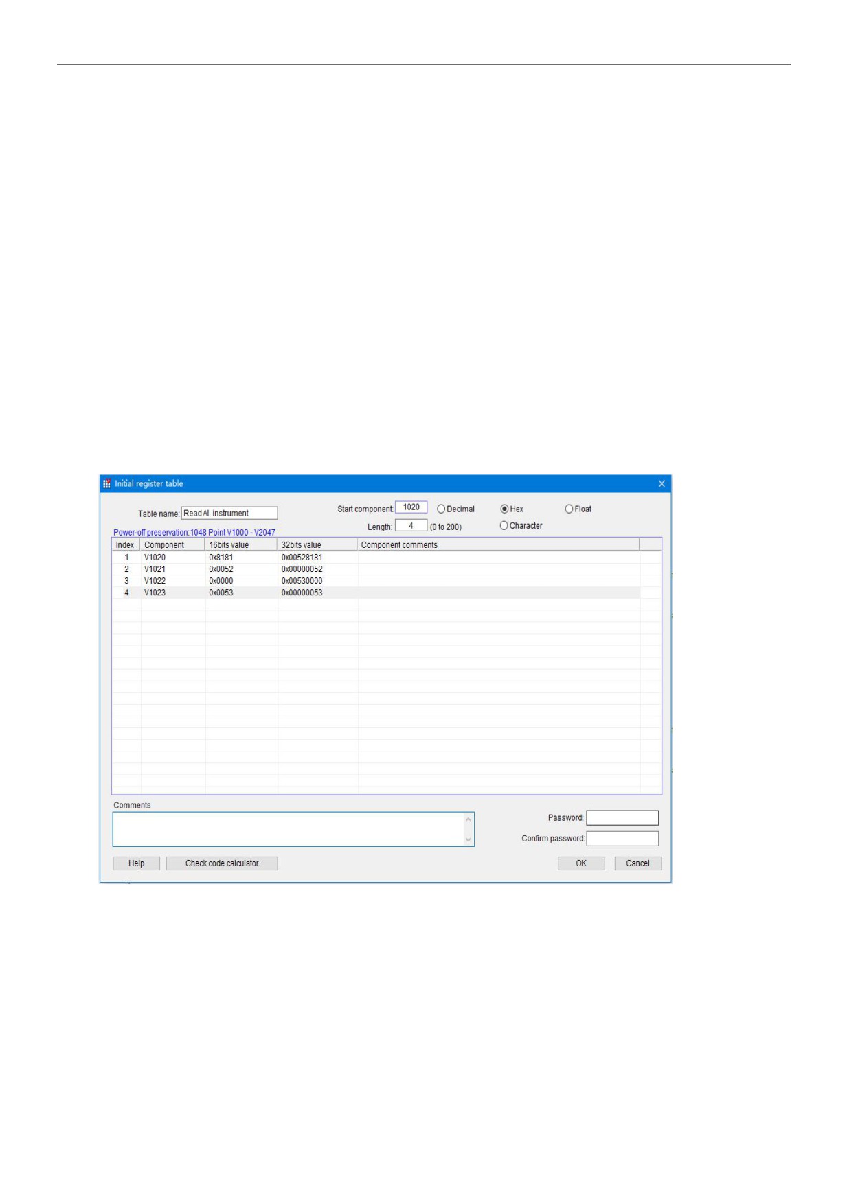
For example, when the values of the register V300 in the PLC are respectively different values, then it sends different data
contents to the serial port, for example:
V300 = 1, then send the 6 bytes data of V1000 ~ 1002 to the communication port;
V300 = 2, then send the 8 bytes data of V1010 ~ 1013 to the communication port;
7.3 Tn>0,Rn>0,for example, communication with YUDIAN instruments by AIBUS
AI instrument uses hexadecimal data format to represent a variety of instruction codes and data. AI instrument only has two
standard communication instruction, one is read instruction, the other is write instruction. As follows:
Read: address code + 52H (82) + parameter code to read + 0 + 0 + check code
Write: address code + 43H (67) + the parameter code to be written + low byte of written data + high byte of written data + check
code
Return data: The instrument returns the following 10 bytes of data no matter for writing or reading:
Measured value PV + setting value SV + output value MV and alarm status + parameter value to be read / written+ check code
11 / 19
In this case, the instrument address is 1, baud rate is 9600, data format is N 8 1. When reading the current temperature, assume
the current temperature is 254.1 ℃ (2541 = 0x9ED), then send and reply data as follows (why the following data is the content
for sending and replying , please refer to the AI instrument manual agreement section):
Send: 81
81
52
00
00
00
53
00
Reply: ED
09
00
00
00
60
00
00
EE
69
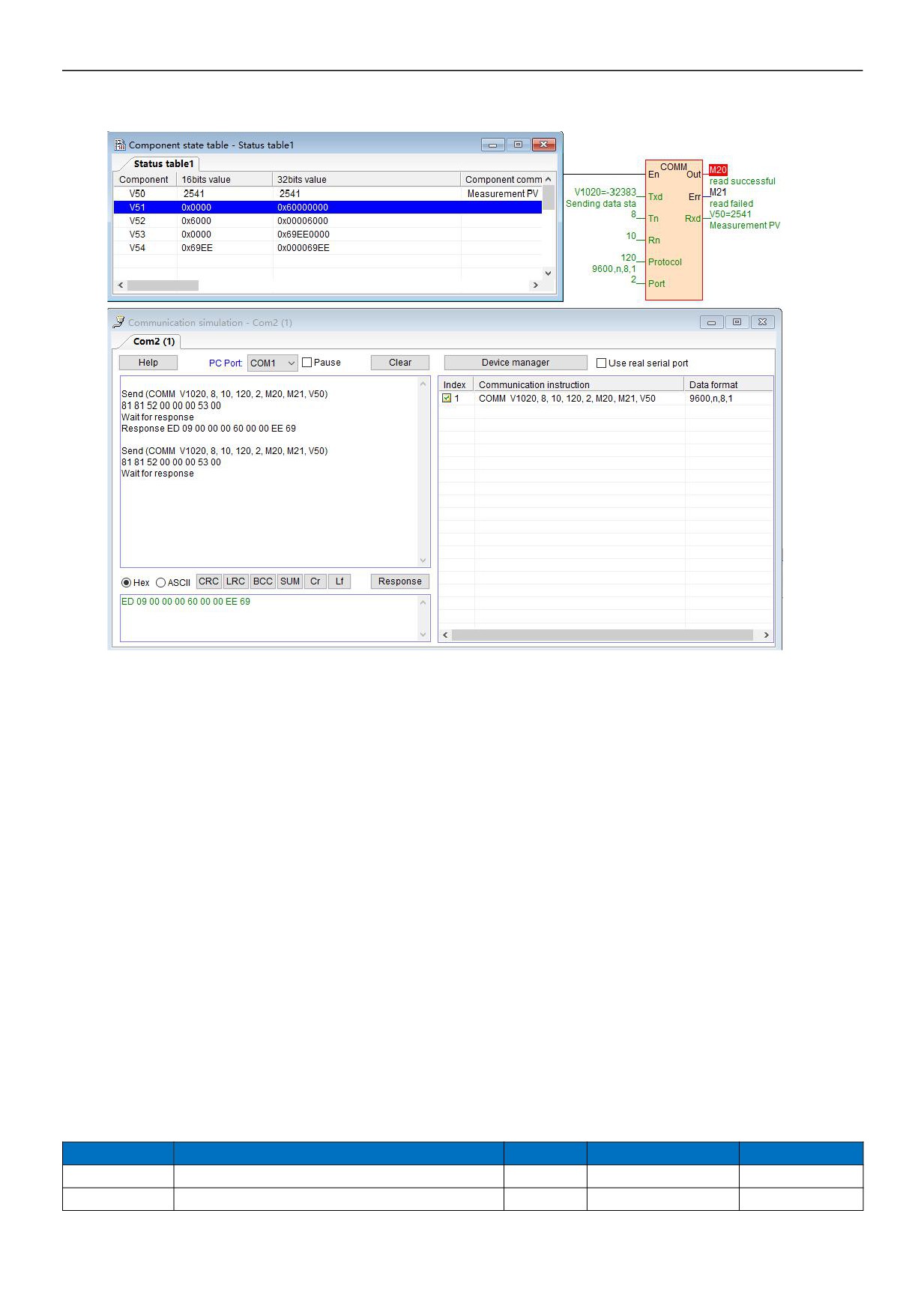
In general, read commands are fixed. HPMaster provides a very convenient initialized data table: it is initial register value table,
the commands which will be sent are filled in the initial register value table, in this case, the starting address is V1020, the length
is 4, a total of 8 bytes, as follows:
00 53
00 00
00 52
81 81
V1023
V1022
V1021
V1020
The COMM instruction has two modes, one is high-low byte mode, first, sending the low-byte data of the start address , then,
sending the high-byte, and so on. The other is the low-byte mode of COMM.LIB. You can double-click to set the COMM instruction,
it only sends the low-byte data of the register. In this example of high-low byte mode, first, send the low-byte 81H of V1020, then
send high-byte 81H, send the low-byte 52H of V1021, then send high-byte 00H of V1021
and so on.
The following is the initial register values table of "read AI instrument commands":
Then according to the regulation of the instrument, we write the COMM instruction, and the simulation is carried out as follows:
12 / 19
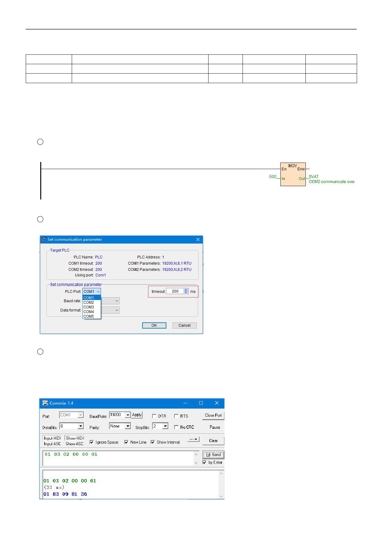
When PLC is running, COMM instruction is scanned,because Tn=8> 0, COMM instruction will send command to communication
port 2 according to the baud rate and data format defined by protocol: 81 81 52 00 00 00 53 00, after sending completed, judge
Rn=10> 0, then it turns into the receiving state. After receiving the command, it will reply the data: ED 09 00 00 00 60 00 00 EE 69,
the data received by the PLC will be placed in the starting register of V50, first it will be stored in the low byte of V50, and then it
will be stored in the high byte of V50 , low byte of V51, high byte of V51
and so on, when receiving data of Rn=10, OUT
terminal is ON, marking the success of this communication
69 EE
00 00
60 00
00 00
09 ED
V54
V53
V52
V51
V50
Received data is arranged as shown above, hexadecimal 09ED is the decimal number 2541, a decimal precision, which is the
actual 254.1 ℃.
8. The system registers of communication timeout time, communication instruction execution interval,
communication port character receiving timeout time and application introduction
Communication timeout time
The unit is ms, the default is 200, that means 200ms, indicating the time which is waiting for the response and replying data from
the slave, after PLC sending commands to communication port. Communication timeout is used for PLC master station, there is
no need to use this communication system register when PLC is used as a slave station.
System register
Note
Read/write
Power-off preserve
Default value
SV45
COM1 and Ethernet communication timeout time, unit: ms
R/W
Yes
200
SV47
COM2 communication timeout time, unit: ms
R/W
Yes
200
13 / 19
SV55
COM3 communication timeout time, unit: ms
R/W
Yes
200
SV57
COM4 communication timeout time, unit: ms
R/W
Yes
200
SV59
COM5 communication timeout time, unit: ms
R/W
Yes
200
In general, the value is default, it is generally used in the situation when some slave instruments response data slowly, for
example, when slave instrument receives the commands from PLC, it will take 0.5 second to reply the data, at this time, you need
to increase the communication timeout time. If you need to increase the communication timeout time, there are two ways for
settings:
1
In the PLC program, use MOV assignment instruction to assign values to system registers, such as COM2
communication timeout time setting.
2
After PLC online, in the menu bar - PLC pull-down option - communication parameters settings-set the communication
timeout time.
3
Serial debugging tools can record the data's interval time from sending to replying. Therefore, it is recommended that
before PLC and instruments communication, you can use the serial port debugging tools to communicate with instruments, so that
we can confirm the instrument station number, baud rate, data format, and the Modbus addresses to be read and written,
response time and so on. In this way, writing PLC communication instruction will be easier. For example, the following figure of
16ms:
14 / 19
Communication instruction execution interval
The interval time defaults to 0, PLC will execute next one immediately after one communication instruction has been executed. If
some devices are not allowed or can not receive such a fast communication frequency, it need to set communication interval
through MOV instruction assignment.
System register
Note
Read/write
Power-off preserve
Default value
SV141
COM1 communication instruction execution interval, unit: ms
R/W
Yes
0
SV833
COM2 communication instruction execution interval, unit: ms
R/W
Yes
0
SV834
COM3 communication instruction execution interval, unit: ms
R/W
Yes
0
SV835
COM4 communication instruction execution interval, unit: ms
R/W
Yes
0
SV836
COM5 communication instruction execution interval, unit: ms
R/W
Yes
0
Note:
z
Communication instruction execution interval is used for PLC master station, there is no need to use this communication
system register when PLC is used as a slave station.
Communication port character receiving timeout time
There will be a situation in the process of communication with instruments, that is, intervals between communication characters of
some instruments are not standard, or a frame data is longer and divided into multiple returns, the intervals between character
frames are larger, so that the PLC can not receive the complete data frames and the instruction will judge that the communication
fails. To this situation, HPMaster conveniently provides a system register used to set the communication port character receiving
timeout time. At this time, the character receiving timeout time can be set. Set the communication port character receiving timeout
time through MOV instruction assignment.
System register
Note
Read/write
Power-off preserve
Default value
SV851
COM1 communication port character receiving timeout time, unit: ms
R/W
Yes
0
SV852
COM2 communication port character receiving timeout time, unit: ms
R/W
Yes
0
SV853
COM3 communication port character receiving timeout time, unit: ms
R/W
Yes
0
SV854
COM4 communication port character receiving timeout time, unit: ms
R/W
Yes
0
SV855
COM5 communication port character receiving timeout time, unit: ms
R/W
Yes
0
Set the communication port character receive timeout time using MOV instruction
Note:
z
Communication port character receiving timeout time is used for PLC master station, there is no need to use this
communication system register when PLC is used as a slave station.
9. When PLC is used as slave station, there is no need to to write any communication program, and
supporting a variety of HMI and configuration software
MPU which is built-in Ethernet port and two serial ports can be extended to the Ethernet port plus five serial ports, each
communication port can be programmed and networked, also it can be used as master or slave. Support the networking ways of 1:
N, N: 1, N: N, support a variety of human-machine interfaces and configuration softwares, also it can be networked with any
third-party device which has communication functions (such as inverters, instruments, bar-code readers, etc.). The figure below
shows the networking way of N:1 when the PLC is used as a slave:
15 / 19
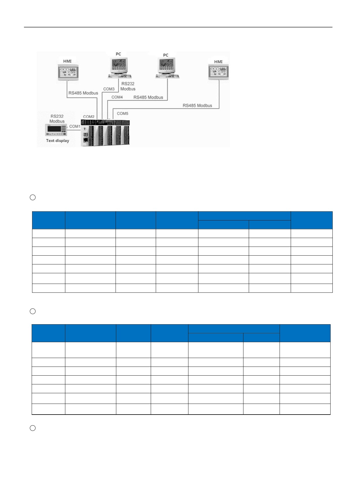
There is no need to write any program when PLC is used as slave, the default parameter is 19200 N 8 2 RTU, station number is 1.
For configuration software and touch screen, which has the built-in HNC driver can directly select HNC driver, if there is no HNC
driver, you can choose Modicon's Modbus driver. The corresponding Modbus communication code table of HNC is as the
following figure:
1
HNC PLC bit component table (equivalent to Modbus address type of 0,1, supporting Modbus function code of 1, 2, 5, 15)
Modbus communication address code
Read/Write
Component
Name
Range
Description
attribute
Hexadecimal
Decimal
X
Digital input
X0~X1023
read
0x0000~0x03FF
0~1023
Y
Digital output
Y0~Y1023
read/write
0x0600~0x09FF
1536~2559
M
Auxiliary relay
M0~M12287
read/write
0x0C00~0x3BFF
3072~15359
T
Timer(coil)
T0~T1023
read/write
0x3C00~0x3FFF
15360~16383
C
Counter(coil)
C0~C255
read/write
0x4000~0x40FF
16384~16639
all be read/some
SM
System Status bit
SM0~SM215
0x4200~0x42D7
16896~17111
be wrote
S
Step relay
S0~S2047
read/write
0x7000~0x77FF
28672~30719
2
HNC PLC register component table (equivalent to Modbus address type of 3, 4, supporting Modbus function code of
3,4,6,16)
Modbus communication address code
Read/Write
Component
Name
Range
Description
attribute
Hexadecimal
Decimal
all be
Used when Modbus
Expansion module
CR
CR0~CR255
read/some be
0x00~0xFF
0~255
accesses expansion
parameters
wrote
module parameters
AI
Analog input register
AI0~AI255
read
0x0000~0x00FF
0~255
AQ
Analog output register
AQ0~AQ255
read/write
0x0100~0x01FF
256~511
V
Internal data register
V0~V14847
read/write
0x0200~0x3BFF
512~15359
TV
Current value of timer
TV0~TV1023
read/write
0x3C00~0x3FFF
15360~16383
Current value of
Only CV48~CV79 are
CV
CV0~CV255
read/write
0x4000~0x40FF
16384~16639
counter
32-bit register
all be read/
SV
System register
SV0~SV900
0x4400~0x4784
17408~18308
some be wrote
3
Description:
z HNC PLC adopts standard Modbus protocol (supporting RTU and ASCII format) it can communicate with all
HMI and configuration softwares that support Modbus protocol.
z HNC PLC's Modbus address number starts from 0, some HMI or configuration software starts from 1, if HMI or
configuration software's Modbus address starts from 0, then it directly uses the communication address, for
16 / 19
example M0 is 0x3072, V0 is 4x0512; If the Modbus address of the HMI or configuration software starts from 1,
the component address number needs to be increased by 1, for example, M0 is 0x3073 [3072 + 1] and V0 is
4x0513 [512 + 1]. The first digit of the address is the Modbus protocol component type (0/1 is bit component,
3/4 is register component, type 0/4 means read-write, type 1/3 means read-only) , the rest of the digit is the
component address number.
10. How to judge the communication failure and program analysis when PLC is used as slave
The communication disconnection alarm program when the master station of PLC communicates with instruments has been
introduced in the above example of "PLCbus communication example introduction: communication between two HNC MPU", then
when the slave station of PLC communicates with the master, if communication line is broken, or the master parameters have
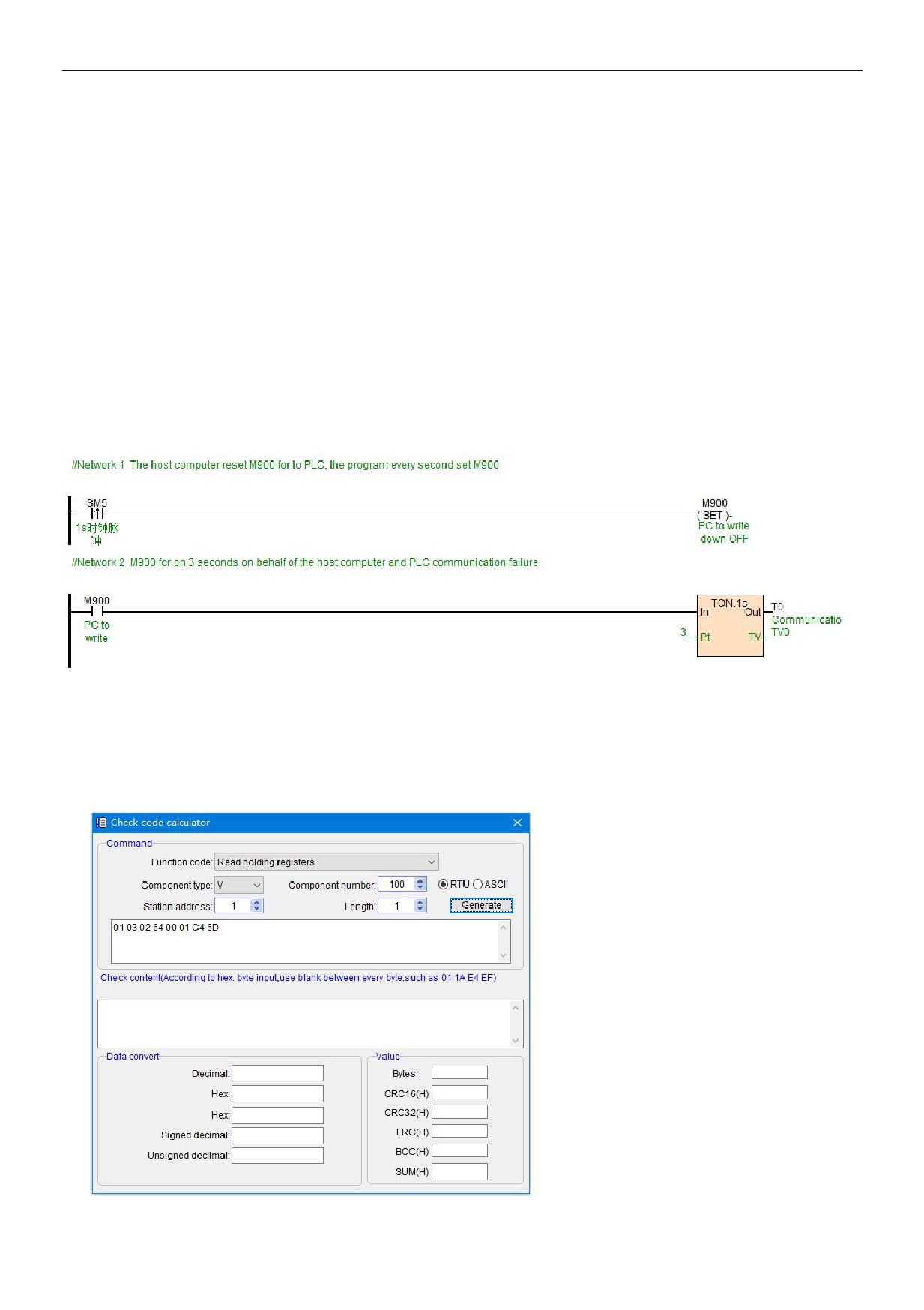
been modified , at this time, as a slave of PLC, how to check the communication disconnection? The following ideas:
The master constantly writes M900 as OFF to PLC, the program sets M900 every second. T0 is used for master communication
failure alarm. If the M900 has a delay of 3 seconds before getting electricity, it means the master does not write M900 to be OFF,
so that we can judge that the communication between the master and the PLC fails.
11. Check-code calculator usage introduction
If you want to use serial debugging tools or master to read the V100 data of HNC PLC, what data commands need to be sent?
According to the previous introduction we know that HNC PLC is built-in Modbus communication protocol, and HPMaster provides
a very convenient tool of check code calculator, the tool can quickly and efficiently calculate the command frame which has been
sent. Open HPMaster-Tools-check code calculator, pop-up the following window:
17 / 19
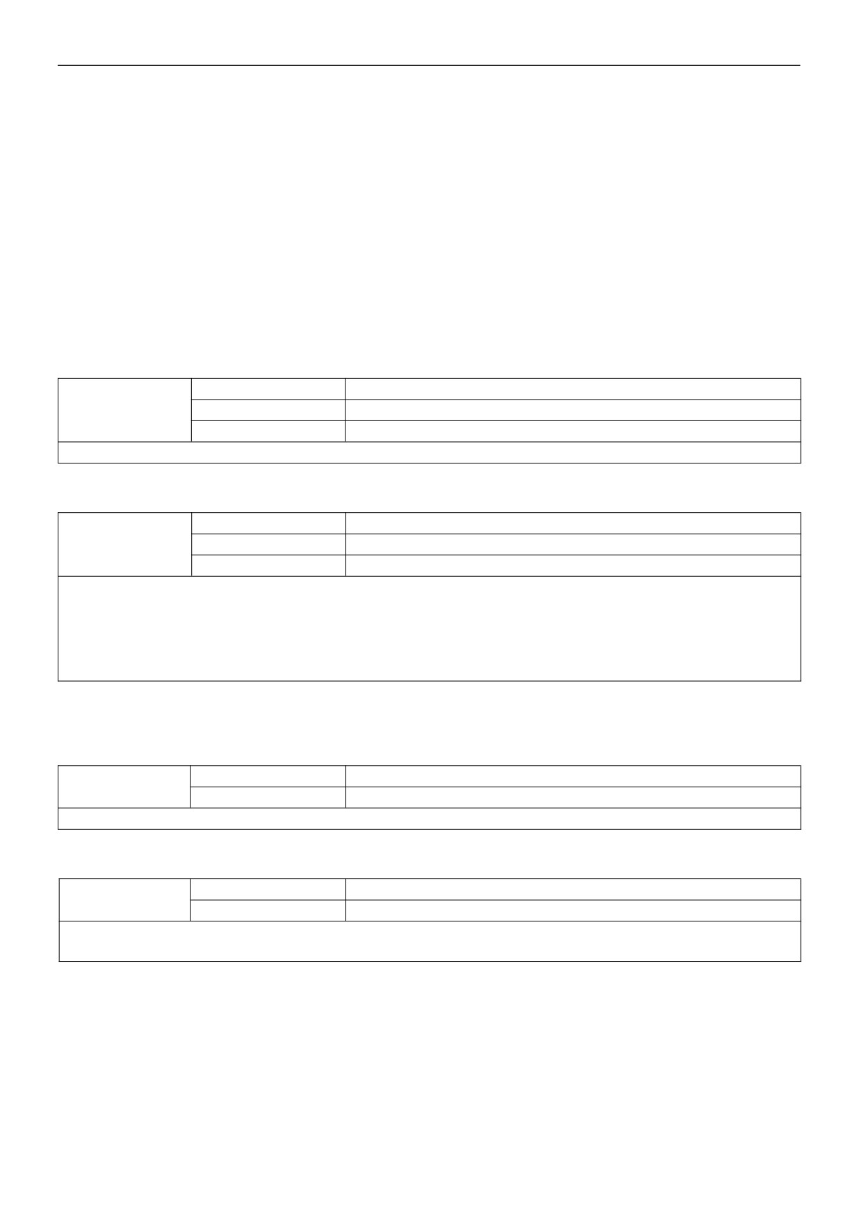
We choose the function code, set the type of components, component number, station number of slave PLC and so on, then click
generate, you can get the command: 01 03 02 64 00 01 C4 6D, the command which sent by master can help to read the V100
value of PLC .
The check code calculator can also carry on the positional notation conversion at the same time, check the data, calculate the
serial data such as CRC, LRC, SUM and other check codes, for communication engineers, this tool is a very convenient
programming assistant.
12. The introduction of supportive baud rate, data format and communication instructions when PLC
communication port is used as a master/slave station
12.1
PLC communication port used as a master station:
Supported by HCS, HCG, HCM series MPU communication port:
Baud rate
1200, 2400, 4800, 9600, 19200, 38400, 57600, 115200
HCS, HCG, HCM MPU
Data format
N,8,2 RTU, E,8,1 RTU, O,8,1 RTU, N,7,2 ASCII, E,7,1 ASCII, O,7,1 ASCII, N,8, 1 RTU
communication port
Communication instruction
MODR / MODW / HWWR / HWRD / COMM / RCV / XMT
Description: MPU' communication port, that is, COM1: RS232 (round-mouth); COM2: RS485 (terminal of A + B- ).
Supported by AE-1C communication expansion module:
Baud rate
1200, 2400, 4800, 9600, 19200, 38400, 57600
AE-1C communication
Data format
N,8,2 RTU, E,8,1 RTU, O,8,1 RTU, N,7,2 ASCII, E,7,1 ASCII, O,7,1 ASCII
module
Communication instruction
MODR / MODW / HWWR / HWRD / COMM
Description:
1, AE-1C module does not support baud rate115200;
2, If AE-1C module uses the MODR/MODW instruction, it will not support the format of N 8 1, so when communicated with the instrument supporting
N 8 1 format, you can deal with the problem through the following three methods:
Method ①: change instrument to 2-bit stop bits;
Method ②: change the calibration method to odd parity check or even parity check;
Method ③: send and receive Modbus protocol through COMM instruction.
12.2 PLC communication port used as a slave station:
Supported by HCS, HCG, HCM series MPU communication port:
Baud rate
1200, 2400, 4800, 9600, 19200, 38400, 57600, 115200
HCS, HCG, HCM MPU
communication port
Data format
N,8,2 RTU, E,8,1 RTU, O,8,1 RTU, N,7,2 ASCII, E,7,1 ASCII, O,7,1 ASCII, N,8, 1 RTU
Description: The default is 19200, N, 8,2 RTU. Generally use the default, without modification.
Supported by AE-1C communication expansion module:
Baud rate
1200, 2400, 4800, 9600, 19200, 38400, 57600
AE-1C communication
module
Data format
N,8,2 RTU, E,8,1 RTU, O,8,1 RTU, N,7,2 ASCII, E,7,1 ASCII, O,7,1 ASCII
Description:
1, The default is 19200, N, 8,2 RTU. Generally use the default, without modification.
18 / 19
13. PLC communication common problems
1
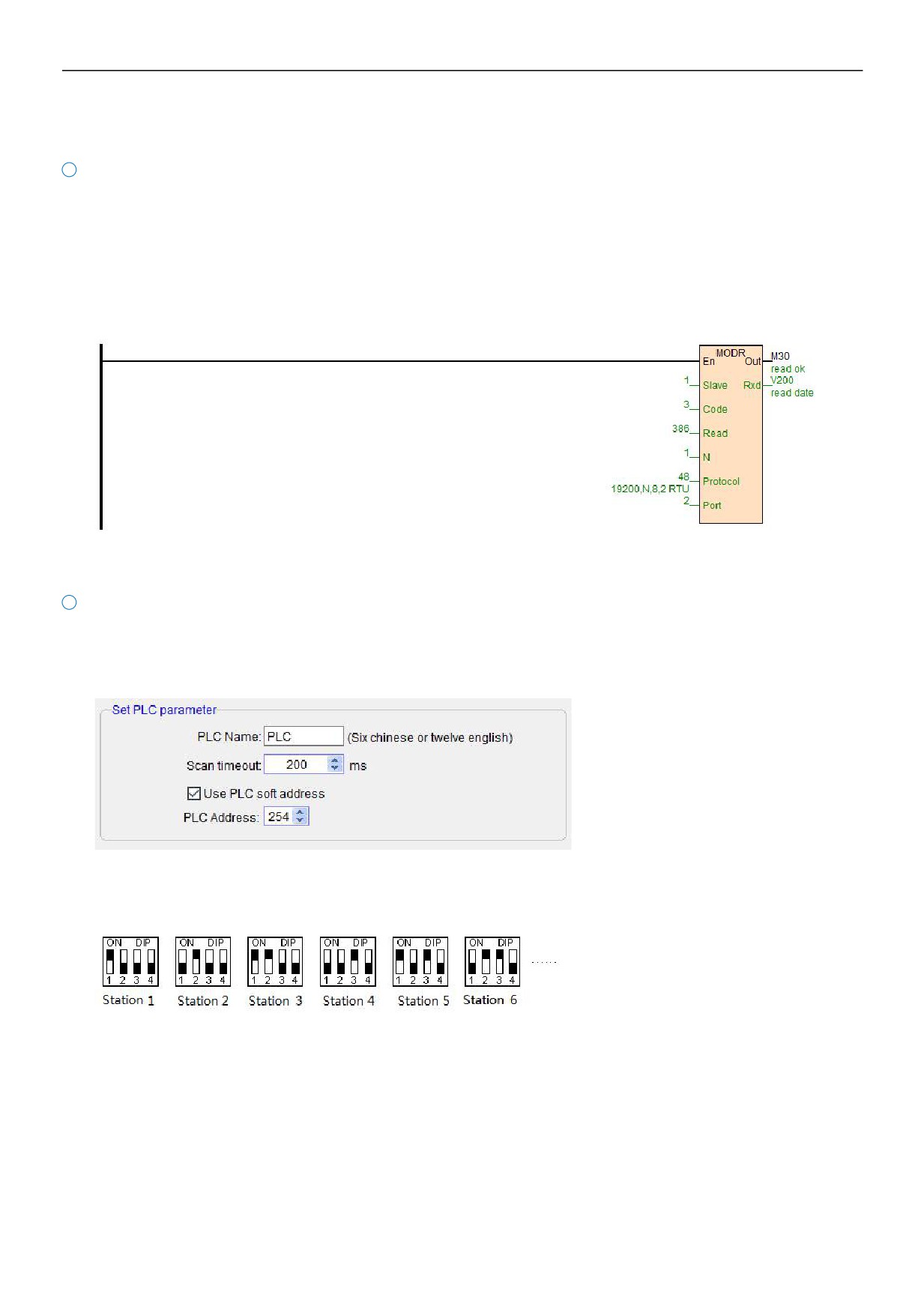
In order to read the register value of instrument, Modbus address is 40001, in HNC Modbus, how much to fill in Read of read
instruction MODR?
A: Fill in 0. The first digit of the address is the Modbus protocol component type (0/1 is bit component, 3/4 is register
component, type 0/4 means read-write, type 1/3 means read-only) , the rest of the digits are component address numbers.
Besides, there is no need to add 1 when HNC PLC reads Modbus device address, so as for the address 40001, it only fills 0
in Read terminal as HNC PLC reading. Similarly, for example, an address is 40387, then as long as fill 386 in HNC
instructions.
2
How to set PLC station number address?
A: Address: 1~254 can be set; PLC address is divided into soft address and hard address, soft address has the highest
priority.
Soft address: Through the programming software-PLC-set PLC parameters, check the use of PLC soft address, address
range is 1-254;
Hard address: The address is set through the 4-bit DIP switch of module hardware, address range 1-15. Hardware address
setting example: