Perkins 4000 Series Model 4016-E61TRS USER’S HANDBOOK (2002)
Perkins 4000 Series
Model 4016-E61TRS
USER’S HANDBOOK
Sixteen cylinder turbocharged gas engines
Publication TSL 4230E, Issue 4
The information is correct at the time of print.
Published in December 2002 by Technical Publications,
Perkins Engines Company Limited, Stafford, ST16 3UB, England
i
This publication is divided into six chapters:
1
General information
2
Engine views
3
Operation instructions
4
Preventive maintenance
5
Gas and engine fluids specification
6
Fault diagnosis
The following pages contain a detailed table of contents
ii
4016-E61TRS
Contents
1 General information
Introduction
1
Safety precautions
2
How to care for your engine
5
Dangers from used engine oils
6
Environmental protection
6
Danger from ‘fluorosilicone’ (Viton) ‘O’ ring seals
7
Practical information for cleaning components
7
Engine preservation
8
Parts and service
8
Service tools
9
Engine identification
10
Engine specifications
11
Performance data
14
2 Engine views
Introduction
15
3 Operating instructions
Introduction
17
How to fill the engine with oil
18
How to fill a CHP type cooling system
19
User’s Handbook, TSL 4230, Issue 4
iii
4016-E61TRS
How to fill a radiator type cooling system
20
4 Preventive maintenance
Maintenance procedures
21
Service schedule
22
How to check the lubricating oil level
26
How to check the coolant level
26
How to change the engine oil and filters
27
How to clean the plug filter fitted in the oil gallery for the piston cooling jets
28
How to check the filter restriction indicator for the closed circuit breather
29
To change the filter element of the closed circuit breather
30
How to check the air cleaner restriction indicator
31
How to change the air filter element and clean the gas mixer
32
How to change the oxygen sensor
33
How to remove a spark plug
34
How to clean, set and fit a spark plug
35
Preparation for equalising bridge pieces and setting valve clearances
36
Bridge piece and valve clearance setting sequence
37
How to equalise bridge pieces
38
How to set valve clearances
39
How to check valve and seat recession
40
5 Gas and engine fluids specification
Gas specification
41
Lubricating oil recommendations
42
Oil and filter change programme
42
Coolant specification
43
6 Fault diagnosis
Introduction
45
Problems and possible causes
46
iv
User’s Handbook, TSL 4230, Issue 4
4016-E61TRS
1
General information
1
Introduction
The 4016-E61TRS is a 16 cylinder turbocharged engine designed by Perkins Engines Company Limited, a
world leader in the design and manufacture of high-performance gas engines.
Perkins approved assembly and quality standards, together with the latest technology, have been applied to
the manufacture of your engine to give you reliable and economic power.
Read and remember the "Safety precautions" on page 2. They are given for your protection and must be used
at all times.
Note: The terms ‘left side’ and ‘right side’ apply when the engine is seen from the flywheel end.
Special tools are required to perform certain operations. A list of those required for the operations described
in this handbook is given in "Service tools" on page 9. Reference to the relevant special tools is also made at
the beginning of each operation, along with those which are universally available (UA) and any additional
specialist supplied equipment (SP) required.
Danger is indicated in the text by two methods:
Warning! This indicates that there is a possible danger to the person.
Caution: This indicates that there is a possible danger to the engine.
Note: Is used where the information is important, but there is not a danger.
User’s Handbook, TSL 4230, Issue 4
1
1
4016-E61TRS
Safety precautions
General
For safe and reliable operation of the engine it is very important that these safety precautions, and those
Warnings and Cautions given throughout this handbook, are observed, and where necessary the special
tools indicated are used.
All safety precautions should be read and understood before operating or servicing the engine.
Improper operation or maintenance procedures are dangerous and could result in accidents, injury or death.
The operator should check before beginning an operation that all the basic safety precautions have been
carried out to prevent accidents occurring.
You must also refer to the local regulations in the country of use.
Note: Some items only apply to specific applications.
Guards
Ensure that guards are fitted over exposed rotating parts, hot surfaces, air intakes, belts or live electrical
terminals (high and low tension).
Protection equipment
Ensure that correct protection equipment is worn at all times.
Always wear protective gloves when using inhibitors or anti-freeze, removing the pressure cap from the
radiator or heat exchanger filler, changing the lubricating oil/filter or changing the electrolyte in the battery.
Always wear ear protection when working in an enclosed engine room.
Always wear suitable eye protection when using an air pressure line.
Always wear protective boots when working on the engine.
Always wear protective headgear when working on or underneath the engine.
Naked flames
Ensure that no smoking or naked flames are lit when checking battery electrolyte, working in the engine
room or when operating or servicing the engine.
Fuel/oil pipes
Ensure that all pipes are regularly checked for leaks.
Ensure that all pipes and the surrounding area are regularly checked for spilt oil (and cleaned up where
necessary).
Always apply suitable barrier cream to hands before any work is carried out.
Gas pipes
Always check for gas/air mixture leaks.
Ensure that the gas line and valves meet local safety standards.
Ensure that the gas line pressure is correct.
Shutdown equipment
Always test that the protection system is working correctly.
When stopping the engine in case of overspeed, high water temperature or low oil pressure should be
provided.
For heat sensors, methane and smoke protectors should be provided (if applicable).
Always be in a position to stop the engine (even remotely).
2
User’s Handbook, TSL 4230, Issue 4
4016-E61TRS
1
Start-up
When working on the engine always ensure that the battery has been disconnected, and that any other
means of accidental start-up has been disabled.
Never start the engine with the governor linkage disconnected.
Do not hold the stop lever in the run position when starting the engine.
Always hold the stop lever in the stop position when cranking only.
Electrical equipment
Always check that electrics are earthed to local safety standards.
Always disconnect the electrical supply to the jacket water heater (if fitted) before working on the engine.
Take care to prevent any danger of electric shock.
Never re-adjust the settings of electronic equipment without reference to the Workshop Manual.
Freezing or heating components
Always use heat resistant gloves and use the correct handling equipment.
Exhaust system
Check the system for leaks.
Ensure that the engine room is correctly ventilated.
Check that all the guards are fitted.
Check that the pipework allows the exhaust gas to escape upwards.
Check that the pipework is supported.
Stopping the engine
1 Disengage the engine load.
2 Run the engine on NO LOAD for 15 minutes before stopping.
Note: This will allow the circulating lubricating oil to dissipate heat from the bearings, pistons, etc. It will also
allow the turbochargers, which run at a very high speed, to slow down while there is still oil flow through the
bearings.
Ensure that the engine is stopped before performing any of the following operations:
Changing the lubricating oil.
Filling or topping up the cooling system.
Beginning any repair work on the engine.
Adjusting belts (where fitted).
Adjusting bridge pieces / valve clearance.
Changing spark plugs.
Changing air or oil filters.
Tightening any fixing bolts.
Flammable fluids
Ensure that these are never stored near the engine.
Ensure that they are never used near a naked light.
User’s Handbook, TSL 4230, Issue 4
3
1
4016-E61TRS
Clothing
Do not wear loose clothing, ties, jewellery, etc.
Always wear steel toe cap shoes/boots.
Always wear the correct head, eye and ear protection.
Always wear suitable overalls.
Always replace a spillage contaminated overall immediately.
Lifting heavy components
Always use the correct lifting equipment.
Never work alone.
Always wear a helmet, if the weight is above head height.
De-scaling solution
Always wear both hand and eye protection when handling.
Always wear overalls and correct footwear.
Waste disposal
Do not leave oil covered cloths on or near the engine.
Do not leave loose items on or near the engine.
Always provide a fireproof container for oil contaminated cloths.
Note: Most accidents are caused by failure to observe basic safety precautions and can be prevented by
recognising potentially dangerous situations before an accident occurs. While there are many potential
hazards that can occur during the operation of the engine which cannot be always be anticipated, and thus a
warning cannot be included to cover every possible circumstance that might involve a potential hazard, by
following these basic principles the danger can be minimised.
4
User’s Handbook, TSL 4230, Issue 4
4016-E61TRS
1
How to care for your engine
This handbook has been written to assist you to maintain and operate your engine correctly, and to carry out
routine servicing of the engine.
The instructions contained in this handbook will, provided that they are correctly carried out, ensure the safe
operation of the equipment.
Before undertaking any work on the engine the relevant chapter in the Workshop Manual should be read and
fully understood.
The information contained within this handbook is based on such information as was available at the time of
print. In line with Perkins Engines Company Limited, Stafford policy of continual development and
improvement that information may change at any time without notice. The engine user should therefore ensure
that he has the latest information before starting work.
Users are respectfully advised that it is their responsibility to employ competent persons to operate the
equipment in the interest of safety.
Operators who are not equipped to undertake major repairs are urged to consult their Perkins distributor.
When not working on the engine, ensure that all covers, blank flanges, doors, etc., are refitted to openings to
prevent the ingress of dirt, etc.
Please quote the engine type and serial number with all your enquiries, see "Engine identification" on page 10.
If any doubt exists regarding the installation, use or application of the engine, the Installation Manual should
be consulted. For further advice contact the Applications Department at Perkins Engines Company Limited,
Stafford.
To obtain the best performance and the longest life from your engine, you must ensure that the maintenance
operations are done at the intervals indicated in the "Service schedule" on page 22. If the engine works in a
very dusty environment or other adverse conditions, certain maintenance intervals will have to be reduced.
Oil change intervals may be changed according to operating experience by agreement with Perkins Engines
Company Limited and subject to oil analysis being performed at regular intervals. Refer to "Oil and filter change
programme" on page 42.
Ensure that all adjustments and repairs are done by personnel who have had the correct training. Perkins
distributors have this type of personnel available. You can also obtain parts and service from your Perkins
distributor.
Note: Where reference is made to ‘A’ and ‘B’ banks of cylinders: ‘A’ bank is to the left and ‘B’ bank is to the
right when viewed from the front of the engine, the crankshaft damper/turbocharger end.
Caution: Do not use mobile phones within 2 meters of the engine as the transmitted signal can affect the
electronic management system of the engine.
User’s Handbook, TSL 4230, Issue 4
5
1
4016-E61TRS
Dangers from used engine oils
Prolonged and repeated contact with mineral oil will result in the removal of natural oils from the skin, leading
to dryness, irritation and dermatitis. The oil also contains potentially harmful contaminants which may result in
skin cancer.
A suitable means of skin protection and washing facilities should be readily available.
The following is a list of ’Health Protection Precautions’, suggested to minimise the danger of contamination.
1 Prevent prolonged and repeated contact with used engine oils.
2 Wear protective clothing, including impervious gloves where applicable.
3 Do not put oily rags into pockets.
4 Prevent contaminating clothes, particularly underwear, with oil.
5 Overalls must be cleaned regularly. Discard unwashable clothing and oil impregnated footwear.
6 First aid treatment should be obtained immediately for open cuts and wounds.
7 Apply barrier creams before each period of work to aid the removal of mineral oil from the skin.
8 Wash with soap and hot water, or alternatively use a skin cleanser and a nail brush, to ensure that all oil is
removed from the skin. Preparations containing lanolin will help replace the natural skin oils which have been
removed.
9 Do NOT use petrol, kerosene, diesel fuel, thinners or solvents for washing the skin.
10 If skin disorder appears, medical advice must be taken.
11 Degrease components before handling if practicable.
12 Where there is the possibility of eye damage, suitable eye protection or a face shield should be worn. An
eye wash facility should be readily available.
Environmental protection
There is legislation to protect the environment from the incorrect disposal of used lubricating oil. To ensure that
the environment is protected, consult your Local Authority who can give advice.
6
User’s Handbook, TSL 4230, Issue 4
4016-E61TRS
1
Danger from ‘fluorosilicone’ (Viton) ‘O’ ring seals
All of the engines ‘O’ ring seals are made from fluorosilicone material.
It is a safe material under normal conditions of operation, but if it is burned the extremely dangerous
hydroflouric acid is produced.
If it is necessary to come into contact with components which have been burnt, follow the precautions below:
Allow the components to cool.
Use Neoprene gloves and a face mask.
Wash the contaminated area with a calcium hydroxide solution and then with clean water.
Disposal of gloves and components which are contaminated must be in accordance with local regulations.
Caution: If there is contamination of the skin or eyes, wash the affected area with a continuous supply of clean
water. Obtain immediate medical attention.
Practical information for cleaning components
Use suitable gloves for protection when components are degreased.
Keep the work area clean and ensure that components are protected from dirt and debris. Ensure that dirt does
not contaminate the fuel system.
Before a component is removed from the engine, clean around the component and ensure that all openings,
disconnected hoses and pipes are sealed.
Remove, clean and inspect each component carefully. If it useable, put it in a clean dry place until needed. Ball
and roller bearings must be cleaned thoroughly and inspected. If the bearings are usable, they must be flushed
in low viscosity oil and protected with clean paper until needed.
Before the components are assembled, ensure that the area is free from dust and dirt as possible. Inspect each
component immediately before it is fitted, wash all pipes and ports, and pass dry compressed air through them
before connections are made.
User’s Handbook, TSL 4230, Issue 4
7
1
4016-E61TRS
Engine preservation
Ex-works preservation treatment
The preservation treatment will give up to 12 months shipping and storage protection under normal enclosed
storage conditions of -15 °C to +55 °C and up to 90% relative humidity.
1 The oil used on engine test will give protection for up to 12 months after despatch from the works.
2 After test the oil is then drained from the sump.
3 The corrosion inhibited anti-freeze at 50% dilution with clean water used on engine test will give protection
for up to 12 months after despatch from the works.
4 After spray painting, all openings in the engine (including points where pipework has been removed and air
cleaner inlets, etc.) are sealed with plastic plugs or covers.
5 The drive face of the flywheel is coated with Valvoline Tectyl 506 preservative.
Parts and service
Service literature
Workshop manuals, installation drawings and other service publications are available from your Perkins
distributor.
Training
Local training for the correct operation, service and overhaul of engines is available at certain Perkins
distributors. If special training is necessary, your Perkins distributor can advise you how to obtain it at the
Perkins Customer Training Department or other main centres.
Service Bulletins
Service procedures and engine design are checked continuously at Perkins Engines. As a result of this
development work, it may become necessary to alter the information in manuals and other service
publications. Between revisions of the literature, all relevant personnel are provided with full details of changes
as they occur. The information is produced as a Service Bulletin; these are supplied to distributors for
distribution as necessary.
8
User’s Handbook, TSL 4230, Issue 4

4016-E61TRS
1
Service tools
The tools and equipment which follow are required for the operations described in this handbook.
Universally available tools
Description
Qty
8 mm Allen key (rocker box capscrews)
1
Screwdriver (bridge piece and valve clearance adjustment)
1
17 mm Combination spanner (bridge piece adjuster locknut)
1
19 mm Combination spanner (rocker adjuster locknut)
1
Feeler gauge set (to set bridge piece and valve clearance)
1
Strap wrench (oil filter removal)
1
30 mm combination spanner (sump drain)
1
Tool box
1
Perkins supplied tools
Part No
Description
Qty
27610190
Spark plug removal tool
1
27610178
Cylinder head spark plug thread cleaning tool
1
T6253/312
Valve and seat recession tool
1
SE253
Engine cranking device
1
User’s Handbook, TSL 4230, Issue 4
9
1
4016-E61TRS
Engine identification
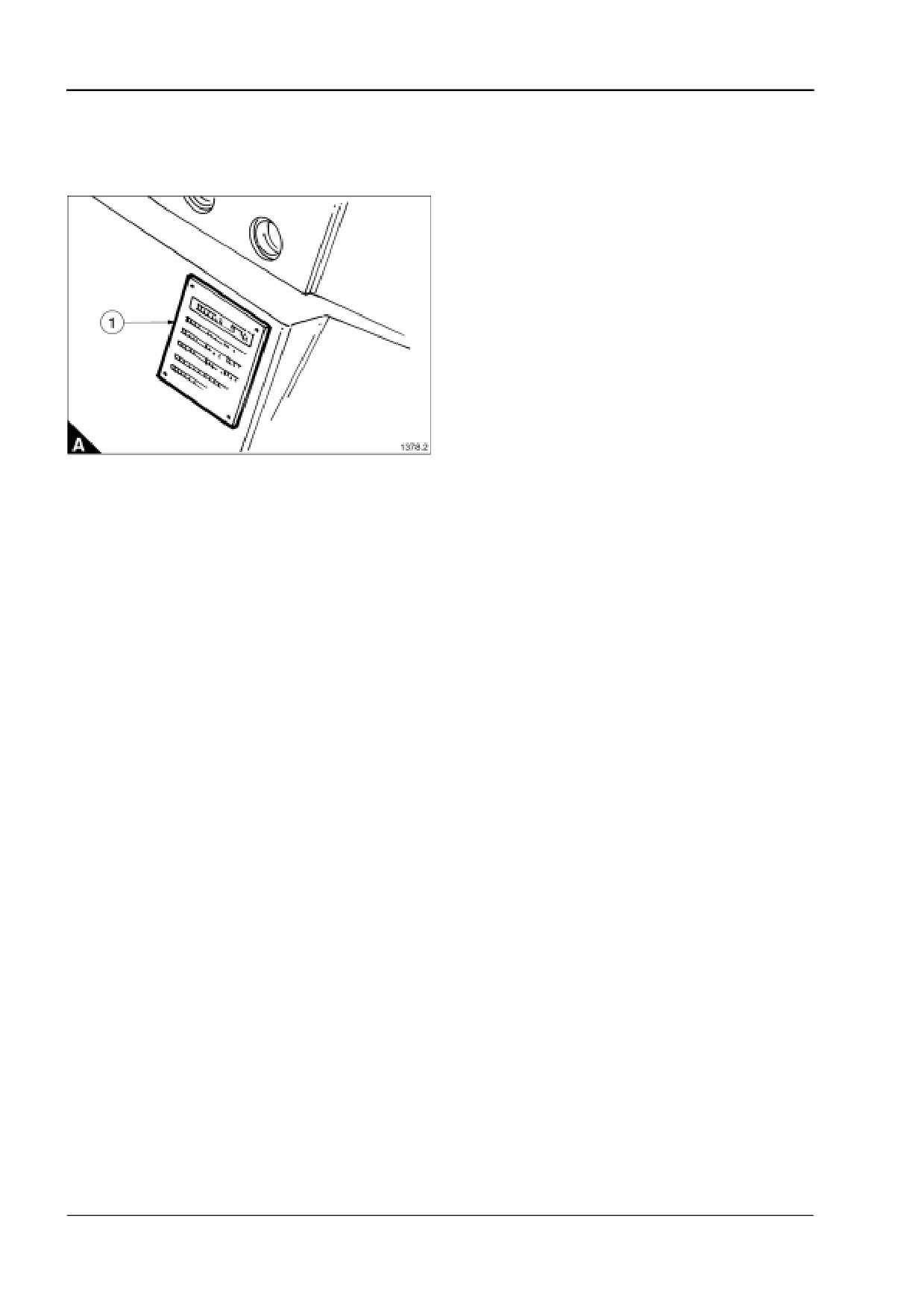
The engine number and its build specification details are given on its data plate.
The data plate is fastened to the crankcase above the flywheel housing on cylinder No. 8, ‘A’ Bank (A1).
10
User’s Handbook, TSL 4230, Issue 4
4016-E61TRS
1
Engine specifications
Engine data
Number of cylinders
16
Cylinder arrangement
60° Vee
Cycle
4 stroke, spark ignition
Induction system
Turbocharged
Compression ratio
12:1
Bore
160 mm
Stroke
190 mm
Cubic capacity
61,123 litres
Direction of rotation
Anti-clockwise viewed on flywheel
Firing order
1A, 1B, 3A, 3B, 7A, 7B, 5A, 5B, 8A, 8B, 6A, 6B, 2A, 2B, 4A, 4B
Estimated total weight (dry)
5,600 kg
Ratings
Electrical ratings are based on average alternator efficiency and are for guidance only (1.0 power factor being
used).
Operating point
Engine speed
1500 rev/min
Ignition timing
25 ° BTDC
Mixture cooler water temperature
40 °C
Cooling water exit temperature
<98 °C
Exhaust emissions
1/2 TA-Luft (NOx) / TA-Luft (NOx)
Fuel data
Fuel type
Natural Gas (UK)
Lower calorific value
34,710 kJ/Sm3 (45,671 kJ/kg)
Density
0,76 kg/Sm3
Stoichiometric air requirement
16 kg/kg
Minimum methane number
75
Cooling system
Recommended coolant:
50% inhibited ethylene glycol or 50% inhibited propylene glycol and 50% clean fresh water. For combined heat
and power systems and where there is no likelihood of ambient temperatures below 10 °C, then clean ‘soft’
water may be used, treated with 1% by volume of Perkins inhibitor (part number OE45350).
Maximum jacket water pressure in crankcase
2 bar
Jacket water data:
Coolant flow
15 kg/s
Coolant exit temperature (max)
98 °C
Coolant entry temperature
84 °C
Charge cooling water data (2nd circuit):
Coolant flow
10 kg/s
Coolant entry temperature (max)
40 °C
Charge cooler
Bar and plate on engine
Coolant pump
not fitted
Maximum static pressure head on coolant inlet above engine crank centre line
7 m
Coolant immersion heater capacity
4 kW (2 off)
User’s Handbook, TSL 4230, Issue 4
11

1
4016-E61TRS
Lubrication system
Recommended lubricating oil (for Natural Gas fuel applications)
ESSO HPC 40
Lubricating oil capacity:
Total system
286 litres
Sump maximum
257 litres
Sump minimum
147 litres
Lubricating oil temperature (maximum to bearings)
105 °C
Lubricating oil pressure (at 85 °C temperature to bearing gallery)
4,5 bar
Oil consumption (after running-in - typically after 250 hours)
0,25 g/kW.hr
Oil flow rate from pump
7,8 l/s
Sump drain plug tapping size
G1
Oil pump
Positive displacement gear pump
Normal operating angles:
Fore and aft
5°
Side tilt
10°
Fuel system
Recommended fuel
Natural Gas LHV at 34,71 MJ/m3
Gas supply pressure
6 kPa to 10 kPa at full rated flow conditions
Carburettor type
Woodward Tecjet 50
Notes:
Gas supplies must be filtered to the same standard as the engine intake air, i.e. maximum particle size not
to exceed 5 microns.
Installation of gas supply and shut-off valves to be in accordance with local regulations.
Fuel consumption gross
Units
1/2 TA-Luft
TA-Luft
Continuous baseload rating
kJ/kWs
2,53
2,47
Mass flow data
Units
1/2 TA-Luft
TA-Luft
Fuel
kg/h
201
198
Volume flow data (100kPa)
Units
1/2 TA-Luft
TA-Luft
Fuel (15 °C)
m3/h
265
261
12
User’s Handbook, TSL 4230, Issue 4

4016-E61TRS
1
Induction system
Emissions data with combustion air temperature of 25 °C at continuous baseload rating.
Emissions data
Units
1/2 TA-Luft
TA-Luft
Oxygen (O2)
%
9.4
9.3
Oxides of nitrogen (NOx) (1)
mg/Nm3
250
500
Carbon monoxide (CO) (1)
mg/Nm3
1100
850
Total hydrocarbons (THC) (1)
mg/Nm3
1411
1372
(1) Figures corrected to 5% O2 in the exhaust stream.
Mass flow data
Units
1/2 TA-Luft
TA-Luft
Combustion air
kg/h
5760
5544
Maximum inlet depression
kPa
4,8
5,9
Exhaust system
Exhaust outlet size
210 mm (internal)
Exhaust data
Units
1/2 TA-Luft
TA-Luft
Exhaust gas flow (wet)
kg/h
5961
5742
Exhaust gas temperature
°C
498
497
Lambda
λ
1,80
1,75
Maximum allowable exhaust back
kPa
6,5
7,0
pressure
Electrical system
Starter motor
24 volts
Starter motor power
16,4 kW
Number of teeth on flywheel
156
Number of teeth on starter motor
12
Minimum cranking speed
120 rev/min
Pull in current of starter motor solenoid
26,8 amps at 24 volts
Hold in current of starter motor solenoid
9 amps at 24 volts
Engine management system
Full electronic engine management system controlling:
Speed governing
Air/Fuel ratio
Start/Stop sequence
Anti-knock
Engine protection and diagnostics
Ignition system
Primary voltage
24 volts
Polarity
Negative earth
Ignition coils
1 per cylinder
Spark plug type
18 mm
Spark plug gap
0,25 mm
Ignition timing
25° BTDC
User’s Handbook, TSL 4230, Issue 4
13
1
4016-E61TRS
Performance data
Note: All data based on operation to ISO 3046/1, BS 5514 DIN 6271 standard reference conditions.
Test conditions
Air temperature - 25 °C
Barometric pressure - 100 kPa
Relative humidity - 30%
General installation
Continuous baseload rating
Designation
Units
50 Hz; 1500 rev/min
1/2 TA-Luft (NOx)
TA-Luft (NOx)
Gross engine power
KW
1042
1042
BMEP gross
Bar
13,6
13,6
Combustion air flow
m3/min
82,7
79,8
Exhaust gas temperature max (after turbo)
°C
498
497
Exhaust gas flow (max)
m3/min
220
212
Overall electrical efficiency
%
38.2
39.2
Mean piston speed
m/s
9,5
9,5
Charge coolant flow
l/s
10
10
Nominal excess air factor (Lambda)
λ
1,80
1,75
Typical Gen Set 25 °C (100 kPa) electrical output
kW
1008
1008
(unit 1.0pf)
Assumed alternator efficiency
%
96.7
96.7
Energy balance
1500 rev/min
1500 rev/min
Continuous baseload rating
Units
%
%
1/2 TA-Luft (NOx)
TA-Luft (NOx)
Energy in fuel (fuel heat of combustion)
kW
2638
100
2574
100
Energy in power output (net) (engine shaft power)
kW
1042
39.5
1042
40.5
Energy to exhaust cooled to 120 °C
kW
688
26.1
673
26.1
(TA Luft)
Energy to coolant (jacket, oil and 1st circuit of c/c)
kW
544
21.0
548
21.3
Sum of useable heat
kW
1340
50.8
1314
51.0
Sum of useable energy
kW
2382
90.3
2356
91.5
Energy to radiation
kW
79
3.0
49
1.9
(surface radiation and other losses)
Energy to charge cooler 2nd circuit
kW
98
3.7
93
3.0
Waste energy from exhaust gas
kW
177
6.7
171
6.6
Note: Not to be used for CHP design purposes. (Indicative figures only). Consult Perkins Engines Company
Limited. Assumes complete combustion.
14
User’s Handbook, TSL 4230, Issue 4
4016-E61TRS
2
Engine views
2
Introduction
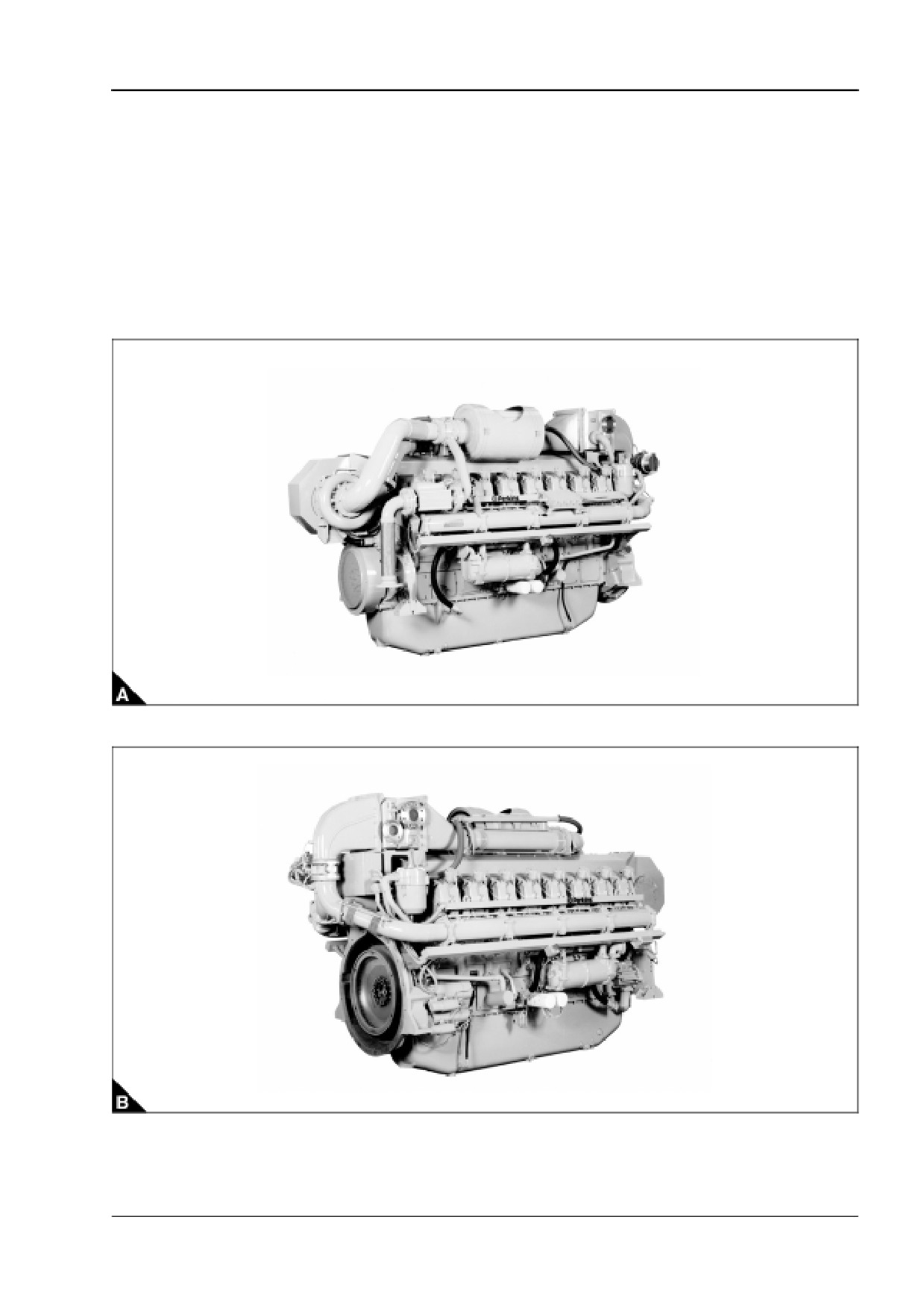
Perkins engines are built for specific applications and the views which follow do not necessarily match your
engine specification.
‘B’ Bank (gearcase end)
‘A’ Bank (flywheel end)
User’s Handbook, TSL 4230, Issue 4
15
This page is intentionally blank
4016-E61TRS
3
Operating instructions
3
Introduction
Information for the mechanical maintenance of the 4016-E61TRS gas engine is given in this User’s Handbook
(TSL 4230) and the Workshop Manual (TSL 4235).
Information on the EMS system which controls all functions on the engine, including oil circuit priming, starting
and stopping sequences is given in the OEM Application, Installation and Commissioning Manual (TSL 4232)
and the Diagnostic Manual (TSL 4233) issue 3.
These publications should be understood and used together for the safe operation of the engine.
Note: For oil and coolant details refer to Chapter 5, Gas and engine fluids specification.
User’s Handbook, TSL 4230, Issue 4
17
3
4016-E61TRS
How to fill the engine with oil
1 Remove the sump drain plug and check that the sump is clean and empty. Refit and tighten the plug.
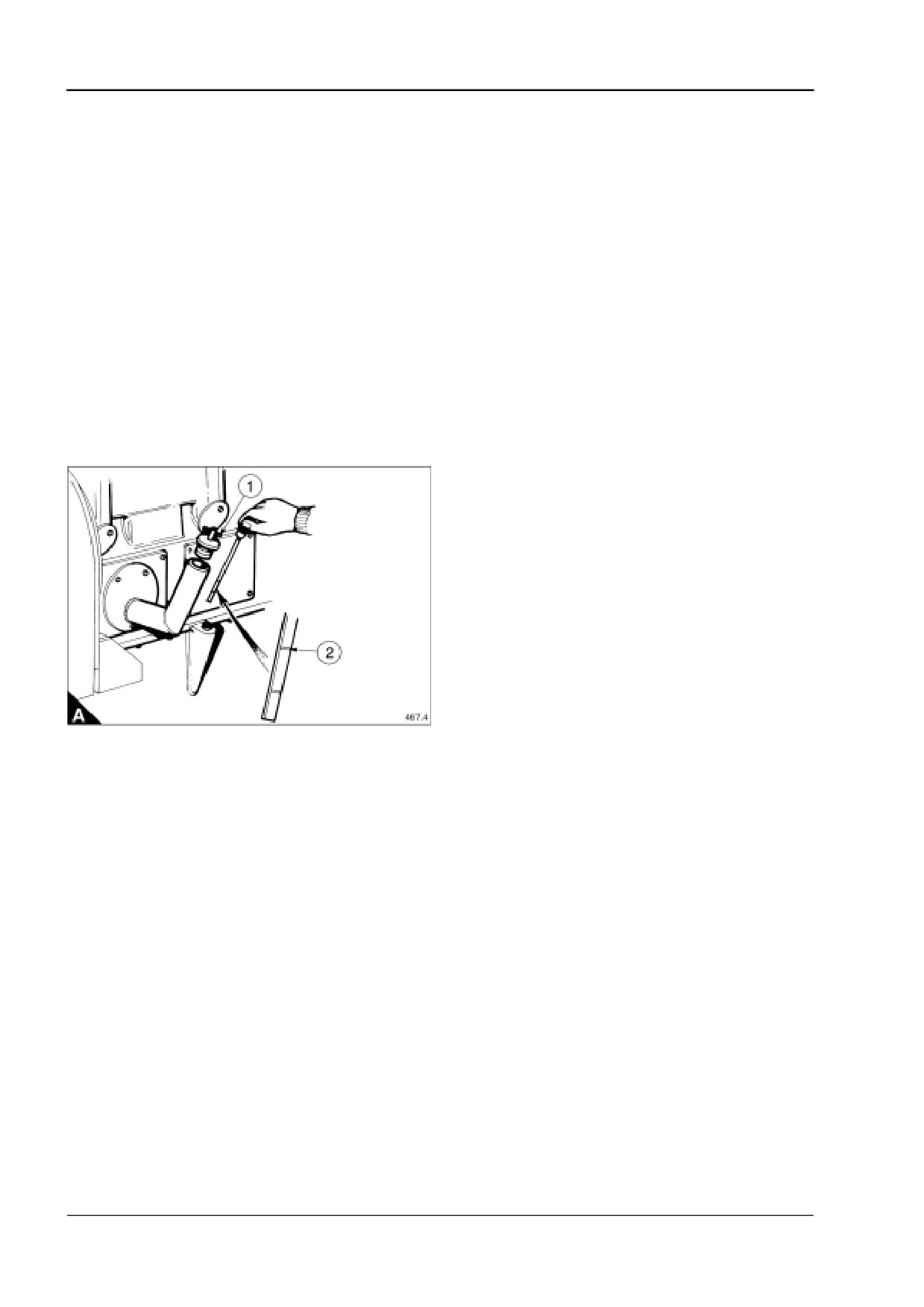
Note: The oil filler and sump dipstick are at the front end of the engine, on the ‘B’ Bank side.
2 Remove the oil filler plug by rotating the T-bar (A1) anti-clockwise.
3 Fill the sump to the maximum mark on the dipstick (A2) with the correct grade of lubricating oil as specified
in "Lubricating oil recommendations" on page 42.
4 Refit the oil filler plug.
Quantity of oil
Maximum
257 litres
Minimum
147 litres
Total system
286 litres
Caution: Use the oil priming sequence before the engine is run, see the OEM Application, Installation and
Commissioning Manual (TSL 4232) issue 3.
Note: When using the engine for the first time, it should be run until it reaches normal working temperature,
stopped, checked for oil leaks and, if necessary, the sump topped up to the full mark (A2) on the dipstick.
18
User’s Handbook, TSL 4230, Issue 4
4016-E61TRS
3
How to fill a CHP type cooling system
The siting of the cooling system filler cap and air vent plugs is dictated by each OEM’s individual installation.
The operator must be aware of their position.
Caution: All trapped air must be vented from the engines cooling system. If an airlock is present on engine
start up localised overheating will occur, possibly causing engine damage.
Note: A solution of clean water and anti-freeze, or clean water and corrosion inhibitor, must be used in the
cooling system. Refer to "Coolant specification" on page 43.
Warning! Always stop the engine and allow the pressurised system to cool before removing the filler cap.
Avoid skin contact with the coolant mixture.
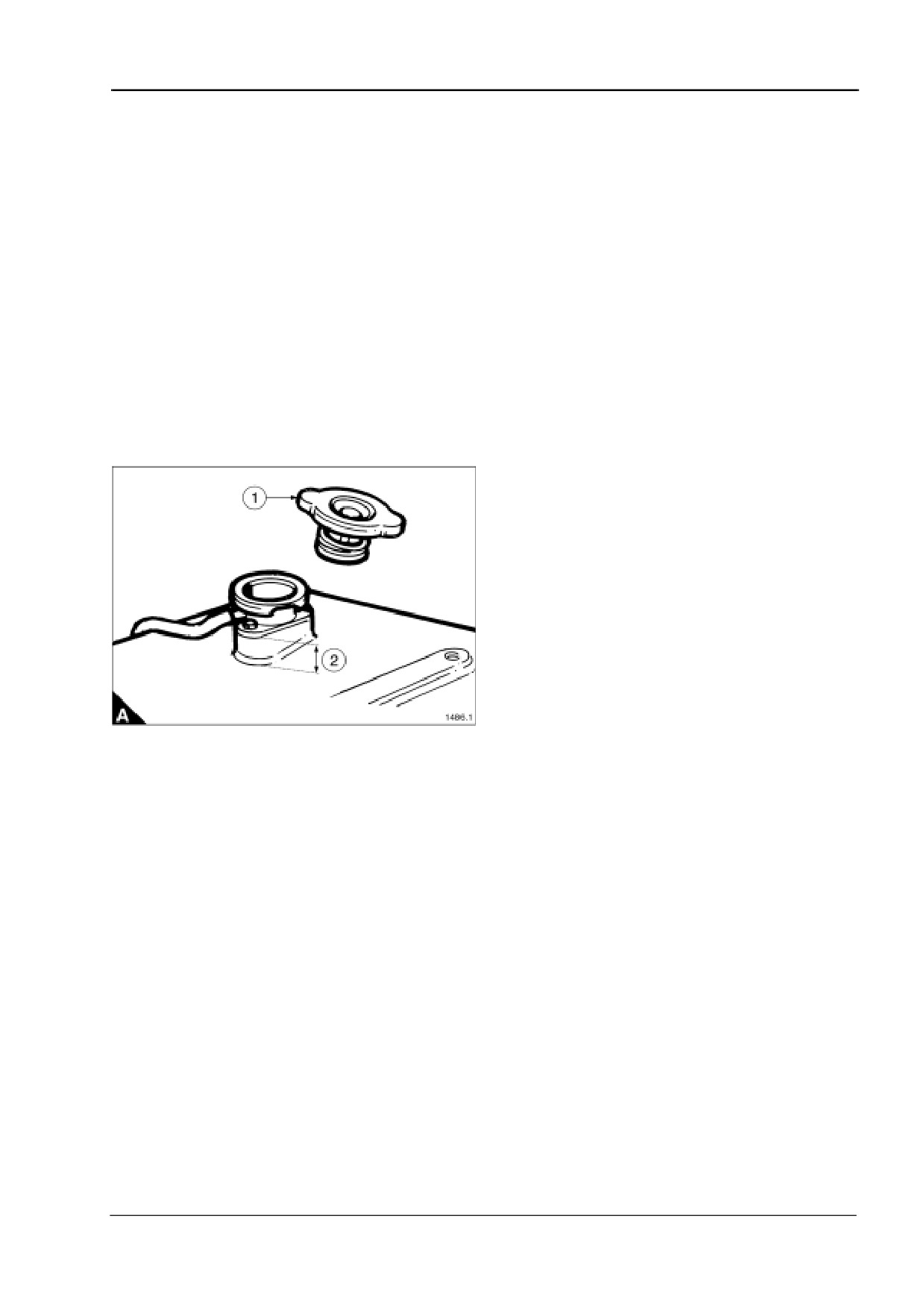
1 Remove the cooling system filler cap (A1).
2 Loosen the appropriate air vent plugs.
3 Fill the cooling system until air free coolant flows from the vent plugs.
4 Stop filling and tighten the vent plugs.
5 Fill the cooling system to 25 mm (1 inch) (A2) below the filler neck.
6 Replace the filler cap.
User’s Handbook, TSL 4230, Issue 4
19
3
4016-E61TRS
How to fill a radiator type cooling system
The siting of the cooling system air vent plugs is dictated by each OEMs individual installation. The operator
must be aware of their position.
Caution: All trapped air must be vented from the engines cooling system. If an airlock is present on engine
start up localised overheating will occur, possibly causing engine damage.
Note: A solution of clean water and anti-freeze, or clean water and corrosion inhibitor, must be used in the
cooling system. Refer to "Coolant specification" on page 43.
Warning! Always stop the engine and allow the pressurised system to cool before removing the filler cap.
Avoid skin contact with the coolant mixture.
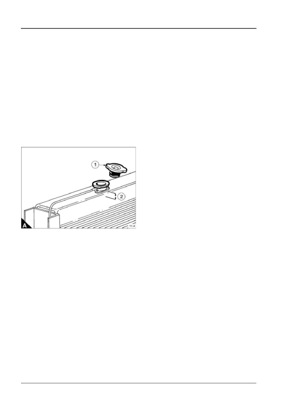
1 Remove the radiator filler cap (A1).
2 Loosen the appropriate air vent plugs.
3 Fill the radiator until air free coolant flows from the vent plugs.
4 Stop filling and tighten the vent plugs.
5 Fill the radiator to 25 mm (1 inch) (A2) below the filler neck.
6 Replace the filler cap.
20
User’s Handbook, TSL 4230, Issue 4
4016-E61TRS
4
Preventive maintenance
4
Maintenance procedures
The service schedule is suitable for an engine working under average conditions.
If your engine is working under particularly dirty or dusty conditions, more frequent servicing will be necessary
particularly in respect of the lubricating oil and air cleaners.
Correct and regular maintenance will help prolong engine life.
Warnings!
Make quite certain that the engine cannot be started before undertaking any maintenance.
This is particularly important in the case of automatically starting generating sets or remote starting
engines.
Personal protective equipment must always be worn.
User’s Handbook, TSL 4230, Issue 4
21
4
4016-E61TRS
Service schedule
Oil and filter change intervals
For engines running on gas to the specification given in "Gas specification" on page 41 and using the approved
lubricating oil given in "Lubricating oil recommendations" on page 42, the oil and filters must be changed after
the first 500 hours of operation.
Subsequent oil and filter changes must be determined using an oil analysis programme. For further details
refer to "Oil and filter change programme" on page 42.
The procedures indicated in the service schedule require reference to the following publications:
User’s Handbook - TSL 4230 (UH)
Workshop Manual - TSL 4235 (WM)
Diagnostic Manual - TSL 4233 (DM)
A service - First 500 hour
Description
Manual
Check EMS logged events and record
DM
Check EMS logged diagnostic codes, record and rectify
Oil and filter change
UH
Clean the filter gauze for the piston cooling jet oil gallery
UH
Equalise bridge pieces and set valve clearances
UH
Check and clean spark plugs, reset gap
UH
B service - 2,000, 6,000, 18,000 and 22,000 hours
Description
Manual
Check EMS logged events and record
DM
Check EMS logged diagnostic codes, record and rectify
Equalise bridge pieces and set valve clearances
UH
Check valve and seat recession
UH
Check and clean spark plugs, reset gap
UH
Closed circuit breather element - renew
UH
Air filter - renew (subject to environmental conditions)
UH
Check emissions, adjust if necessary
DM
C service - 4,000 and 20,000 hours
Description
Manual
Check EMS logged events and record
DM
Check EMS logged diagnostic codes, record and rectify
Clean the filter gauze for the piston cooling jet oil gallery
UH
Equalise bridge pieces and set valve clearances
UH
Check valve and seat recession
UH
Check and clean spark plugs, reset gap
UH
Breather element - renew
UH
Air filter - renew (subject to environmental conditions)
UH
Calibrate oxygen sensor
UH - DM
Check emissions, adjust if necessary
DM
22
User’s Handbook, TSL 4230, Issue 4

4016-E61TRS
4
D service - 8,000 and 24,000 hours
Description
Manual
Check EMS logged events and record
DM
Check EMS logged diagnostic codes, record and rectify
Clean the filter gauze for the piston cooling jet oil gallery
UH
Equalise bridge pieces and set valve clearances
UH
Check valve and seat recession
UH
Check and clean spark plugs, reset gap
UH
Breather element - renew
UH
Air filter - renew (subject to environmental conditions)
UH
Charge cooler - clean and fit new gasket
WM
Test sensors and protection systems annually
DM
Check coolant anti-freeze/inhibitor strength annually
UH
Calibrate oxygen sensor, renew if necessary
UH - DM
Calibrate turbine inlet temperature interface module
DM
Check emissions (adjust if required)
DM
Magnetic pick-ups - clean and adjust
WM
Check and calibrate ignition timing
DM
E service - 10,000, 14,000, 26,000 and 30,000 hours
Description
Manual
Check EMS logged events and record
DM
Check EMS logged diagnostic codes, record and rectify
Equalise bridge pieces and set valve clearances
UH
Check valve and seat recession
UH
Check and clean spark plugs, reset gap
UH
Breather element - renew
UH
Air filter - renew (subject to environmental conditions)
UH
Calibrate oxygen sensor, renew if necessary
UH - DM
User’s Handbook, TSL 4230, Issue 4
23

4
4016-E61TRS
F service - 12,000 and 28,000 hours
Description
Manual
Check EMS logged events and record
DM
Check EMS logged diagnostic codes, record and rectify
Clean the filter gauze for the piston cooling jet oil gallery
UH
Equalise bridge pieces and set valve clearances
UH
Check valve and seat recession
UH
Check and clean spark plugs, reset gap
UH
Breather element - renew
UH
Air filter - renew (subject to environmental conditions)
UH
Calibrate oxygen sensor, renew if necessary
UH - DM
Check emissions, adjust if necessary
DM
G service - 16,000 hours
Description
Manual
Check EMS logged events and record
DM
Check EMS logged diagnostic codes, record and rectify
Equalise bridge pieces and set the valve clearances
UH
Check valve and seat recession
UH
Check and clean spark plugs, reset gap
WM
Breather element - renew
WM
Air filter - renew (subject to environmental conditions)
WM
Cylinder heads - renew
WM
Charge cooler - clean and fit new gasket
WM
Test sensors and protection systems annually
DM
Check coolant anti-freeze/inhibitor strength annually
UH
Replace oxygen sensor
UH - DM
Calibrate interface module for turbine inlet temperature
DM
Check emissions, adjust if necessary
DM
Oil cooler assembly - overhaul
WM
Turbocharger - renew
WM
Clean gas mixer (see air filter change)
UH
Magnetic pick-ups - clean and adjust
WM
Check and calibrate ignition timing
DM
Inspect ignition coils
UH
24
User’s Handbook, TSL 4230, Issue 4
4016-E61TRS
4
H service - 32,000 hours
Description
Manual
Check EMS logged events and record
DM
Check EMS logged diagnostic codes, record and rectify
Clean the filter gauze for the piston cooling jet oil gallery
UH
Equalise bridge pieces and set valve clearances
UH
Check and clean spark plugs, reset gap
UH
Breather element - renew
UH
Air filter - renew (subject to environmental conditions)
UH
Cylinder heads - renew
WM
Charge cooler - clean and fit a new gasket
WM
Test sensors and protection systems annually
DM
Check coolant anti-freeze/inhibitor strength annually
WM
Calibrate oxygen sensor, renew if necessary
UH - DM
Calibrate interface module for turbine inlet temperature
WM - DM
Check emissions, adjust if necessary
DM
Oil cooler assembly - overhaul
WM
Turbocharger - renew
WM
Clean gas mixer (see air filter change)
UH
Magnetic pick-ups - clean and adjust
WM
Check and calibrate ignition timing
DM
Governor actuator - renew throttle valve
WM
Fuel valve/tecjet - renew
WM
Butterfly valve - overhaul
WM
Inspect ignition coils
UH
Pistons, rings and liners - renew
WM
Big end bearings - renew
WM
Small end bearings - inspect and renew if necessary
WM
Camshaft, camshaft bushes and cam-follower assembly - renew
WM
Starter motors - renew
WM
Front and rear crankshaft oil seals - inspect and renew if necessary
WM
Pushrods - check for wear and straightness
WM
Timing gears - inspect
WM
Torsional vibration dampers - renew
WM
Exhaust manifold - check and renew if necessary
WM
Notes:
Maintenance schedule from 32,000 hrs to 64,000 hrs is the same as 20,000 to 32,000 hrs.
At 64,000 hrs operation consult Perkins Engines Company Limited, Stafford, with reference to major
overhaul and service exchange engine components.
User’s Handbook, TSL 4230, Issue 4
25
4
4016-E61TRS
How to check the lubricating oil level
1 Stop the engine and wait 5 minutes to allow the oil to drain into the sump.
2 Withdraw the dipstick and wipe clean.
3 Insert the dipstick and wait 2 seconds.
4 Withdraw the dipstick and check the level against the high and low marks.
5 If necessary, put more oil into the sump. Use the same grade and specification as that already in the system.
Caution: Do NOT overfill.
How to check the coolant level
Warning! Always stop the engine and allow the pressurised system to cool before removing the filler cap.
Avoid skin contact with the coolant mixture.
1 Remove the filler cap.
2 The coolant level should be 25 mm (1”) below the top of the filler neck.
Caution: If coolant is added to the system during the service, it must consist of the same original mixture as
used to fill the system.
3 Refit the filler cap.
26
User’s Handbook, TSL 4230, Issue 4
4016-E61TRS
4
How to change the engine oil and filters
1 Place a container with a capacity of 250 litres (35 gal) under the sump drain plug.
2 Remove the sump drain plug and allow the oil to drain into the container.
3 Place a container with a capacity of 5 litres (1 gal) under the filters to catch the oil which will be released as
they are removed.
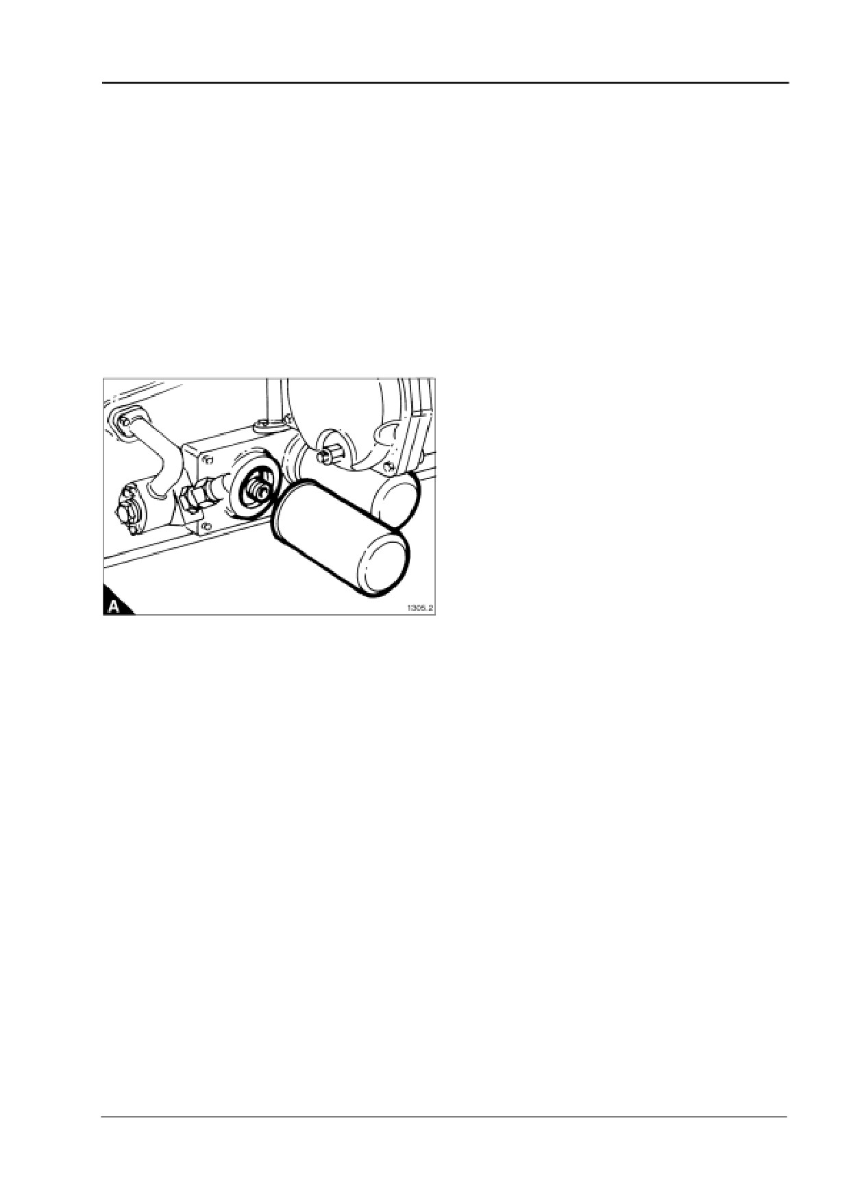
4 Remove the oil filters using a strap wrench, turning the filter anti-clockwise (A).
5 Clean the sealing faces and the threaded bosses of the oil filter header.
6 Lightly lubricate the sealing ring of the new filters with engine oil.
7 Screw each filter up to the header using firm hand pressure.
8 Refit the sump drain plug and refill the engine with the correct grade of lubricating oil as given in "Lubricating
oil recommendations" on page 42.
Caution: Use the oil priming sequence before the engine is run, see the OEM Application, Installation and
Commissioning Manual (TSL 4232).
User’s Handbook, TSL 4230, Issue 4
27
4
4016-E61TRS
How to clean the plug filter fitted in the oil gallery for the piston cooling jets
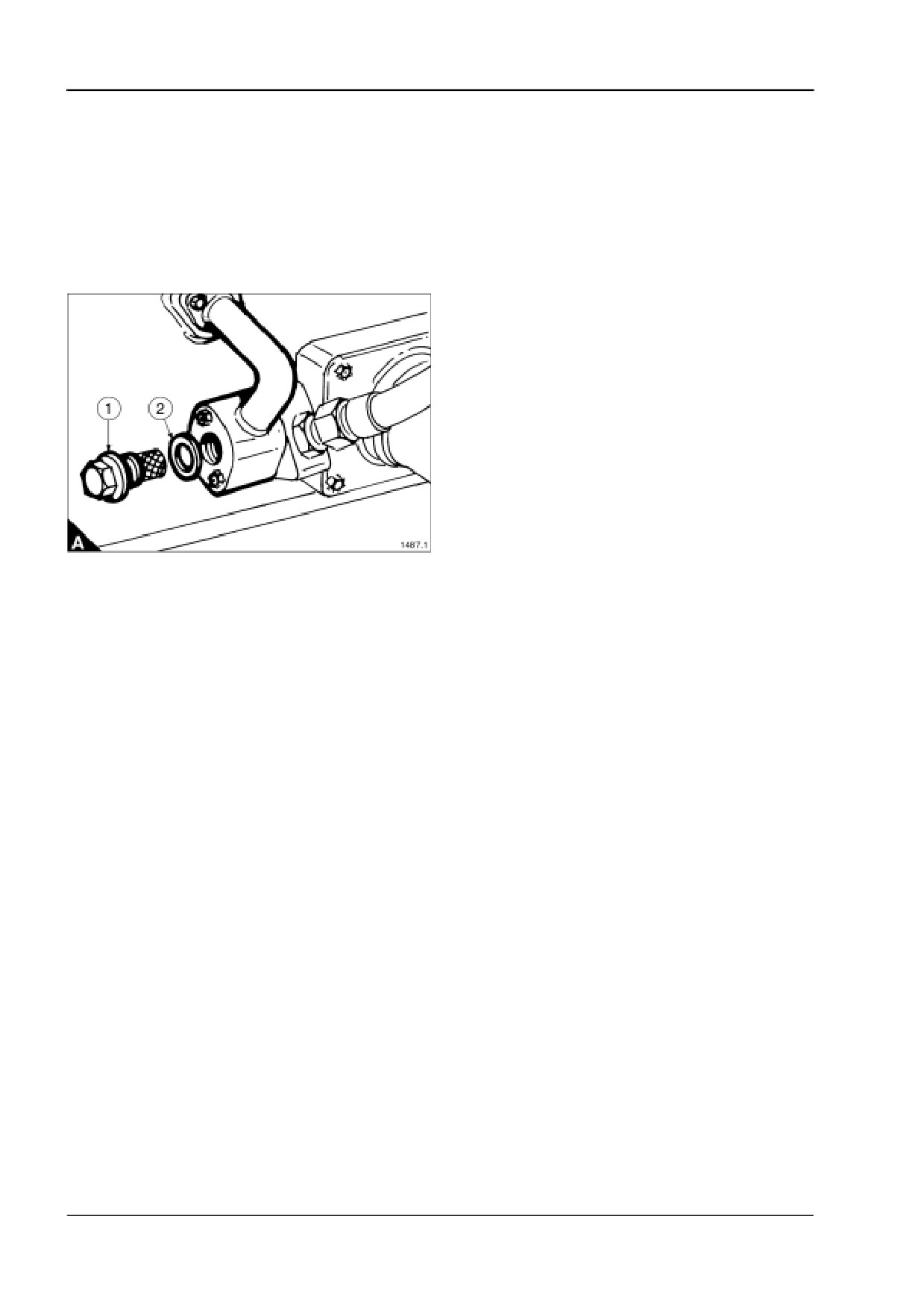
1 Remove the plug filter (A1).
2 Clean the filter using a suitable solvent, if necessary use compressed air to remove small particles from the
gauze.
3 Refit the plug filter (A1), complete with a new sealing washer, part number 036620 (A2), and tighten to a
torque of 70 Nm (50 lbf ft).
Caution: Use the oil priming sequence before the engine is run, see the OEM Application, Installation and
Commissioning Manual (TSL 4232).
28
User’s Handbook, TSL 4230, Issue 4
4016-E61TRS
4
How to check the filter restriction indicator for the closed circuit breather
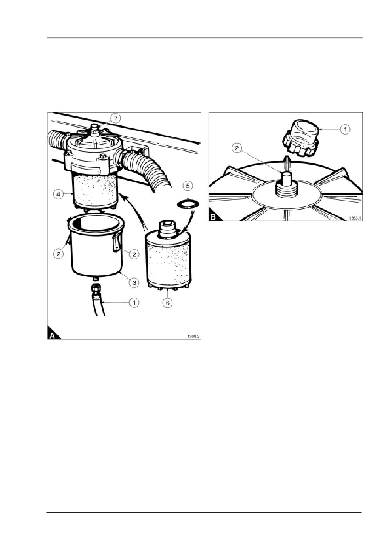
1 Examine the clear plastic cover (A7) on the breather filter. If the red indicator button is not showing the filter
is in serviceable condition.
2 When the filter reaches its contamination limit the red restriction indicator button will show. At this point the
filter element must be renewed, see "To change the filter element of the closed circuit breather" on page 30.
3 When the filter element has been changed, reset the indicator button: remove the clear plastic cover (B1),
press the indicator button (B2) and refit the cover.
User’s Handbook, TSL 4230, Issue 4
29
4
4016-E61TRS
To change the filter element of the closed circuit breather
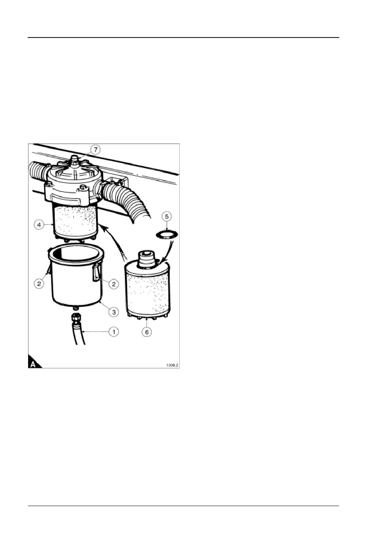
1 Disconnect the oil drain pipe (A1).
2 Release the three retaining clips (A2) and lift the filter container (A3) from the filter body.
3 Pull the filter element (A4) down from the filter body and discard it.
4 Clean the oil deposits from the filter container and the filter body.
5 Fit the sealing/retaining ‘O’ ring (A5) to the new filter element (A6).
6 Push the filter element into its location in the filter body.
7 Fit the filter container to the filter body. When locking down the retaining clips check the container is squarely
seated on the filter body.
8 Refit the oil drain pipe (A1).
30
User’s Handbook, TSL 4230, Issue 4
4016-E61TRS
4
How to check the air cleaner restriction indicator
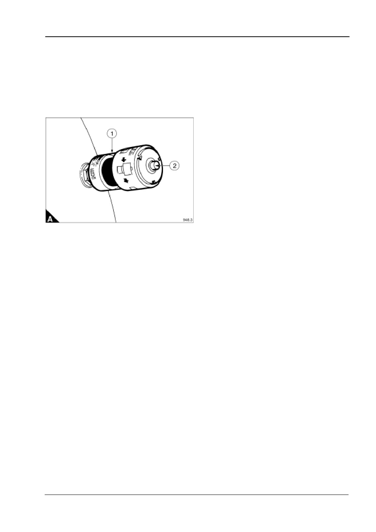
1 Examine the middle section of the restriction indicator (A1). It will remain clear while the air cleaner is in
serviceable condition.
2 When the filter reaches its contamination limit the restriction indicator will sense the change in manifold
pressure and the middle section will change to red.
3 At this point the air filter must be changed, see "How to change the air filter element and clean the gas mixer"
on page 32.
4 When the air filter has been changed reset the indicator by pressing the button (A2).
User’s Handbook, TSL 4230, Issue 4
31
4
4016-E61TRS
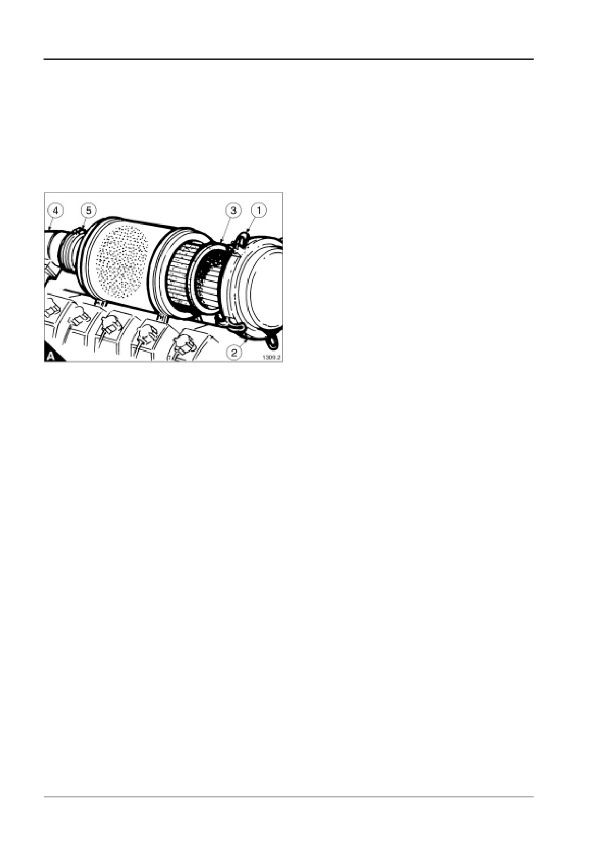
How to change the air filter element and clean the gas mixer
1 Release the five over-centre catches (A1) and remove the air filter end cover (A2).
2 Pull out the filter element (A3).
3 Clean any dust accumulation from inside the air filter body and the gas mixer (A4) using a clean cloth. If
necessary remove the coupling hose (A5) to give access.
4 Fit a new filter element into the filter body.
5 Fit the end cover locating it in the filter element and on the filter body, then lock down the over-centre
catches.
32
User’s Handbook, TSL 4230, Issue 4
4016-E61TRS
4
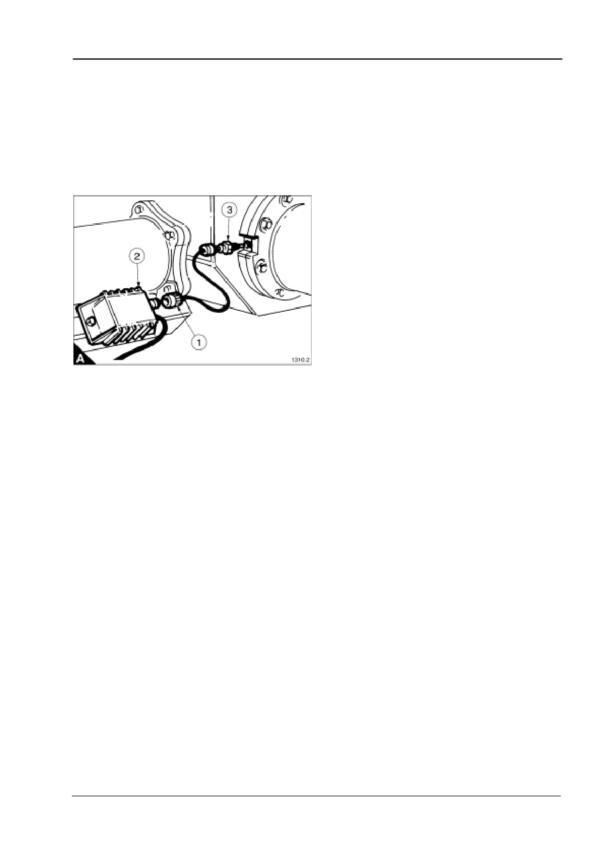
How to change the oxygen sensor
1 Disconnect the multi-pin plug (A1) on the oxygen sensor power cable from the connector on the oxygen
sensor interface (A2).
2 Remove the oxygen sensor (A3) from the turbocharger outlet.
3 Fit the new oxygen sensor into the turbocharger outlet tighten it down to 25 Nm (18 lbf ft).
4 Reconnect the multi pin plug (A1).
Note: Calibration of the EMS system will be required when the oxygen sensor is changed. Refer to the
Diagnostic Manual (TSL 4233).
User’s Handbook, TSL 4230, Issue 4
33
4
4016-E61TRS
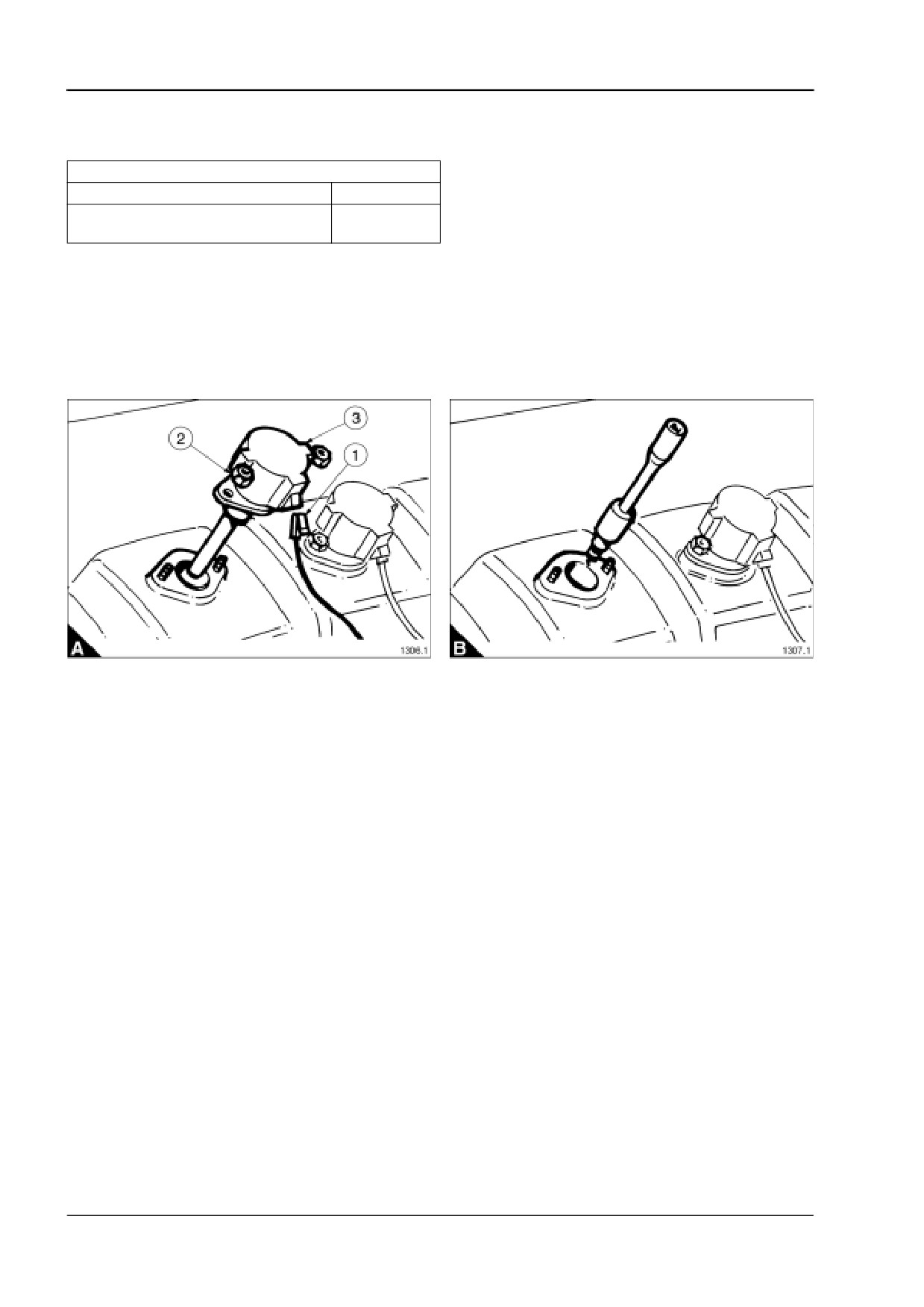
How to remove a spark plug
Special requirements
Special tools
Description
Part number
Spark plug removal socket and extension
27610190
bar
1 Disconnect the power lead (A1) to the ignition coil.
2 Remove the two retaining nuts (A2).
3 Pull the combined ignition coil/plug cap (A3) out of the rocker cover.
4 Remove the spark plug (B).
Note: Store the spark plugs in their cylinder order as the combustion deposits on the plugs will give a guide
to the conditions in each cylinder.
34
User’s Handbook, TSL 4230, Issue 4
4016-E61TRS
4
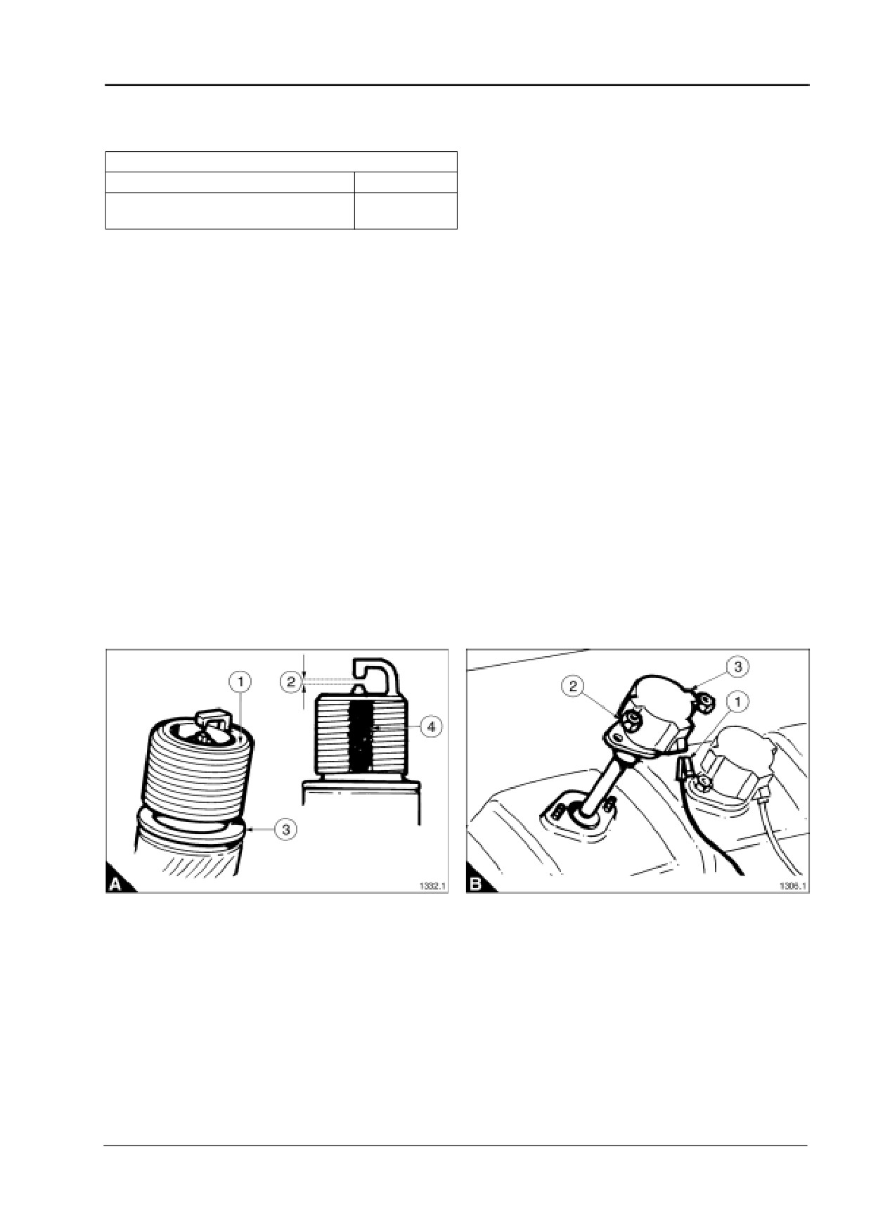
How to clean, set and fit a spark plug
Special requirements
Special tools
Description
Part number
Cylinder head spark plug thread cleaning
27610178
tool
1 Clean any carbon/ash deposits from the spark plug thread and ceramic insulator using a suitable solvent
and a dry cloth.
Note: A light coating of ash evenly deposited on the electrodes indicates the plug is in good condition with a
clean burning mixture.
2 Clean any loose ash deposit from the end of the spark plug (A1) using a nylon brush.
Caution: Do not use a metal brush to clean a spark plug as the porcelain around the centre electrode will be
scratched allowing ash deposits to build rapidly on the roughened surface causing plug failure.
3 Set the spark plug gap to 0,25 mm (0.010 in) (A2).
Note: The centre and ground electrodes of the spark plug are tipped with a hard surface which must not be
filed or cleaned using abrasive paper.
4 Every time a spark plug is refitted the sealing washer (A3) must be renewed. Use sealing washer part
number Y98/00038.
Caution: The spark plug should be finger tightened into the cylinder head, if resistance is felt clean the plug
thread in the cylinder head using a thread chaser. Never use a thread tap.
5 Apply a very small amount of Poly Butyl Cuprysil grease to the thread of the spark plug (A4).
6 Fit the spark plug carefully locating it in the cylinder head. Tighten down finger tight, then torque to 50 Nm
(35 lbf ft).
7 Refit the ignition coil (B3) and tighten the retaining nuts (B2) to 13,5 Nm (10 lbf ft).
8 Refit the power lead (B1).
User’s Handbook, TSL 4230, Issue 4
35
4
4016-E61TRS
Preparation for equalising bridge pieces and setting valve clearances
Special requirements
Special tools
Description
Part number
Engine cranking device
SE253
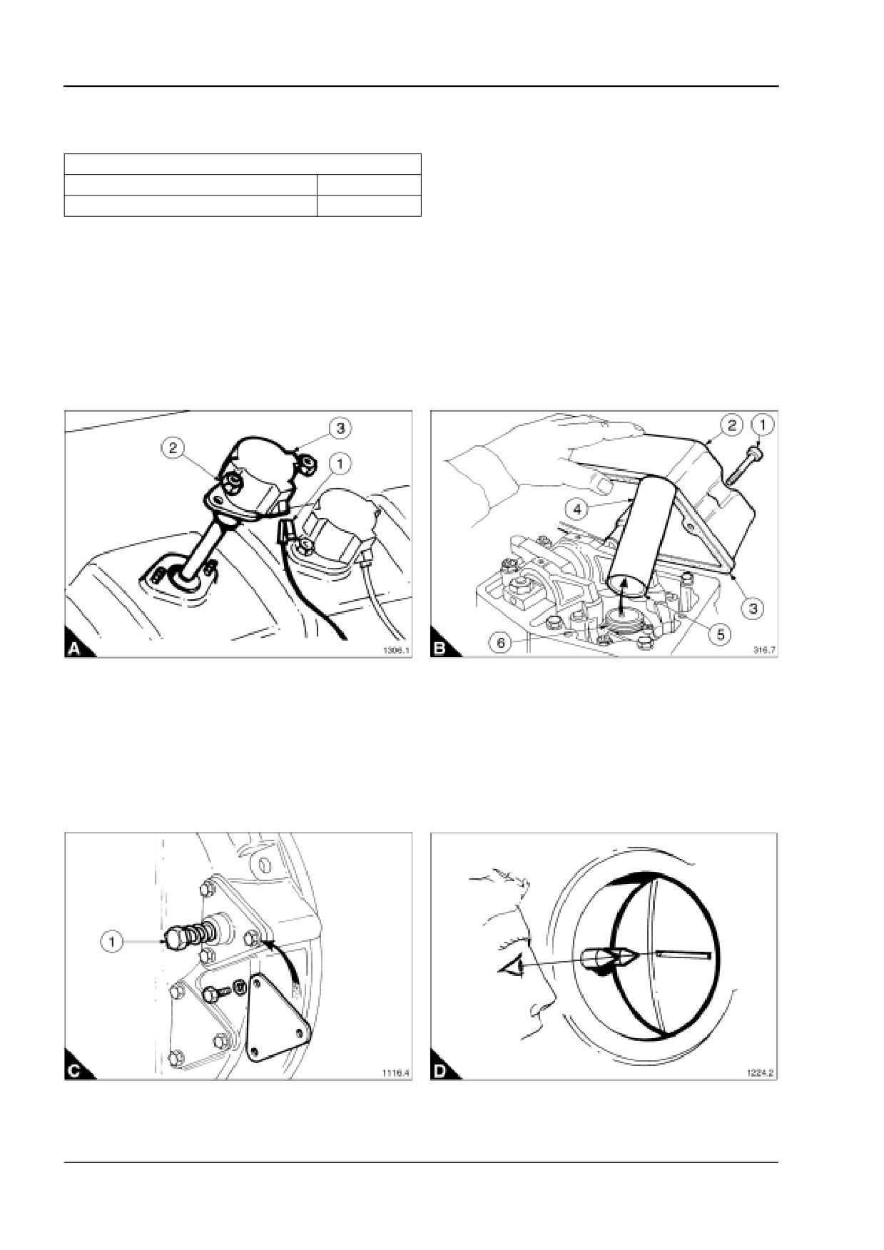
1 Disconnect the power lead (A1) from the ignition coil.
2 Remove the two retaining nuts (A2).
3 Pull the combined ignition coil/plug cap (A3) out of the rocker cover.
4 Remove the four retaining capscrews (B1) from each rocker cover (B2).
5 Lift off the rocker cover, remove and discard the gasket (B3).
6 Pull the spark plug cover tube (B4) out of the cylinder head.
Warning! When refitting the spark plug tube (B4), the internal chamfer (B5) must be fitted against the ‘O’ ring
(B6).
7 To rotate the engine to the positions required for this procedure fit the engine cranking device to the spare
starter motor mounting in the flywheel housing (C).
8 Using a socket and ratchet wrench press against the spring loaded bolt head (C1) until the pinion engages
with the flywheel gear, then crank the engine to the desired position. Refer to "Bridge piece and valve
clearance setting sequence" on page 37.
9 The engines flywheel is marked giving the T.D.C. (top dead centre) position of each cylinder. They are
viewed through an inspection hole in the flywheel housing. To get an accurate reading line up by eye the tip of
both pointers with the marks on the flywheel (D).
36
User’s Handbook, TSL 4230, Issue 4
4016-E61TRS
4
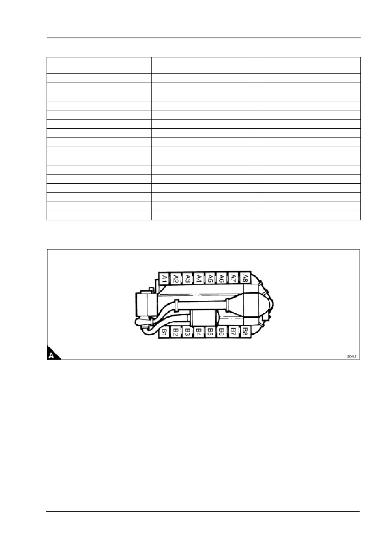
Bridge piece and valve clearance setting sequence
T.D.C.
Set bridge piece and valve
Valves rocking on cylinder No.
(Top Dead Centre)
clearance on cylinder No.
A1 - A8
A8
A1
B1 - B8
B8
B1
A3 - A6
A6
A3
B3 - B6
B6
B3
A7 - A2
A2
A7
B7 - B2
B2
B7
A5 - A4
A4
A5
B5 - B4
B4
B5
A1 - A8
A1
A8
B1 - B8
B1
B8
A3 - A6
A3
A6
B3 - B6
B3
B6
A7 - A2
A7
A2
B7 - B2
B7
B2
A5 - A4
A5
A4
B5 - B4
B5
B4
Note: Where reference is made to ‘A’ and ‘B’ banks of cylinders: ‘A’ bank is to the left and ‘B’ bank is to the
right when viewed from the front of the engine, the crankshaft damper/turbocharger end.
User’s Handbook, TSL 4230, Issue 4
37
4
4016-E61TRS
How to equalise bridge pieces
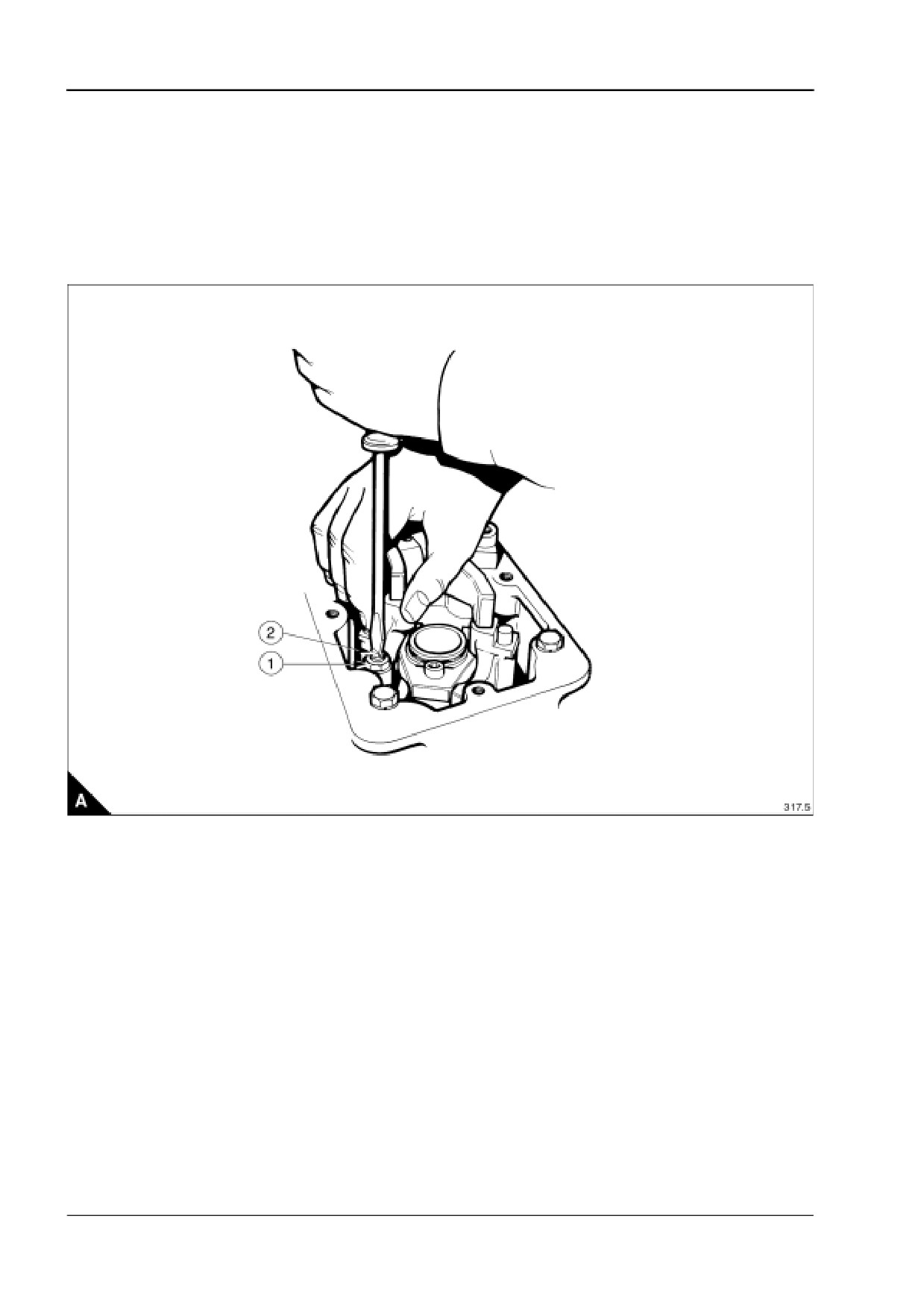
1 Rotate the engine to the position given in "Bridge piece and valve clearance setting sequence" on page 37.
Caution: Check the inlet and exhaust rockers have clearance on the bridge piece.
2 Loosen the locknut on the bridge piece (A1).
3 Screw the adjuster (A2) out until the fixed side of the bridge piece rests on its valve.
4 Hold the top edge of the bridge piece and screw the adjuster down until it touches the valve.
5 Tighten the locknut to a torque of 35 Nm (25 lbf ft) without moving the adjuster.
38
User’s Handbook, TSL 4230, Issue 4
4016-E61TRS
4
How to set valve clearances
Special requirements
Special tools
Description
Part number
Feeler gauges
UA
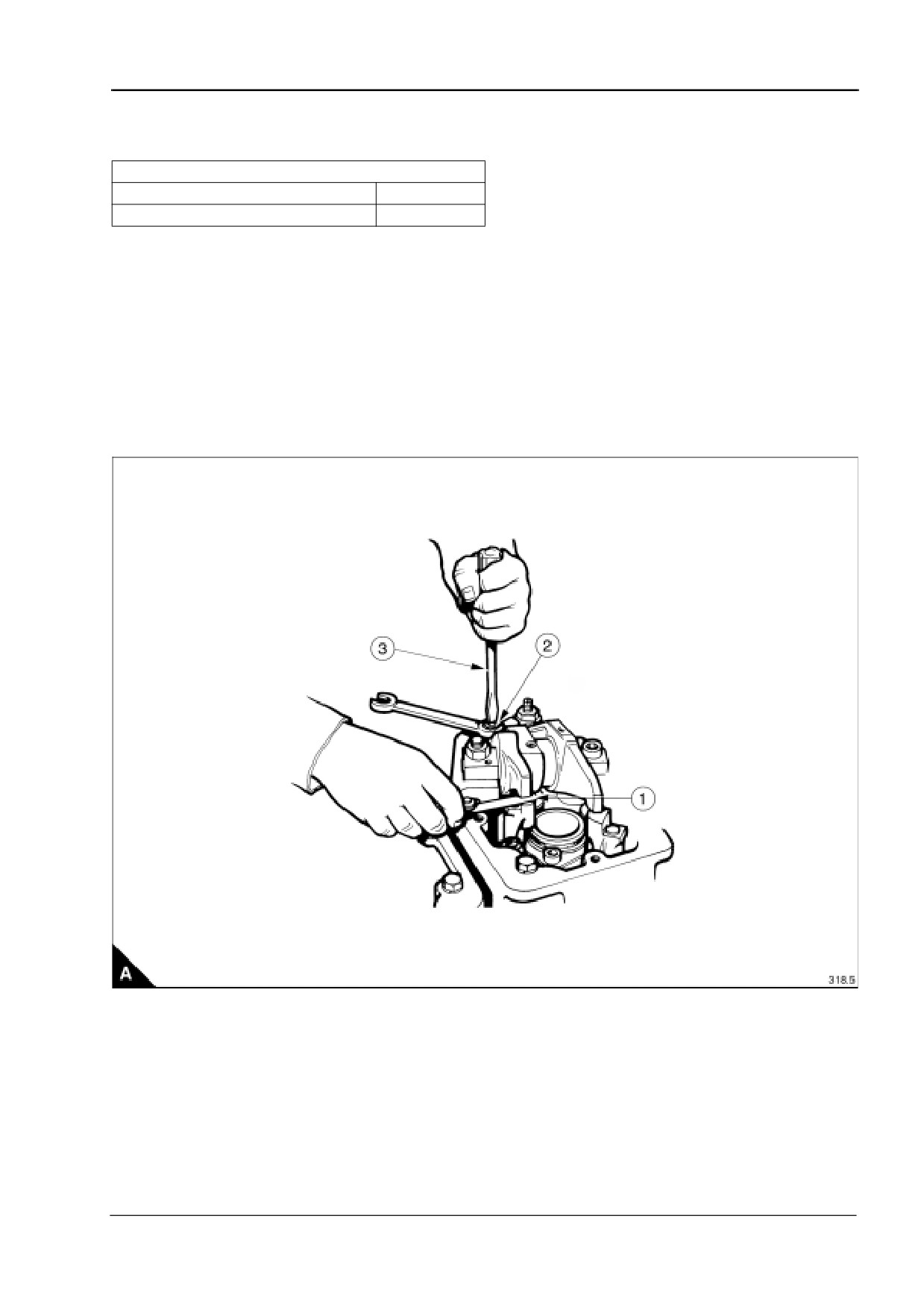
1 Check the clearance using a feeler gauge.
Note: The inlet and exhaust valve clearance is 0,4 mm (0.016 in).
2 To set the valve clearance loosen the locknut (A2).
3 Place the feeler gauge (A1) between the rocker and bridge piece.
4 Screw the adjuster (A3) up or down making the feeler gauge a slide fit.
5 Tighten the locknut to a torque of 50 Nm (35 lbf ft) without moving the adjuster.
6 Refit the spark plug cover tube and rocker cover. Use a new gasket.
7 Refit the spark plug, refer to "How to clean, set and fit a spark plug" on page 35.
8 Refit the ignition coil. Tighten the retaining nuts to 19,0 Nm (14 lbf ft).
User’s Handbook, TSL 4230, Issue 4
39
4
4016-E61TRS
How to check valve and seat recession
Special requirements
Special tools
Description
Part number
Description
Part number
Valve seat recession checking tool
T6253/312
Feeler gauges
UA
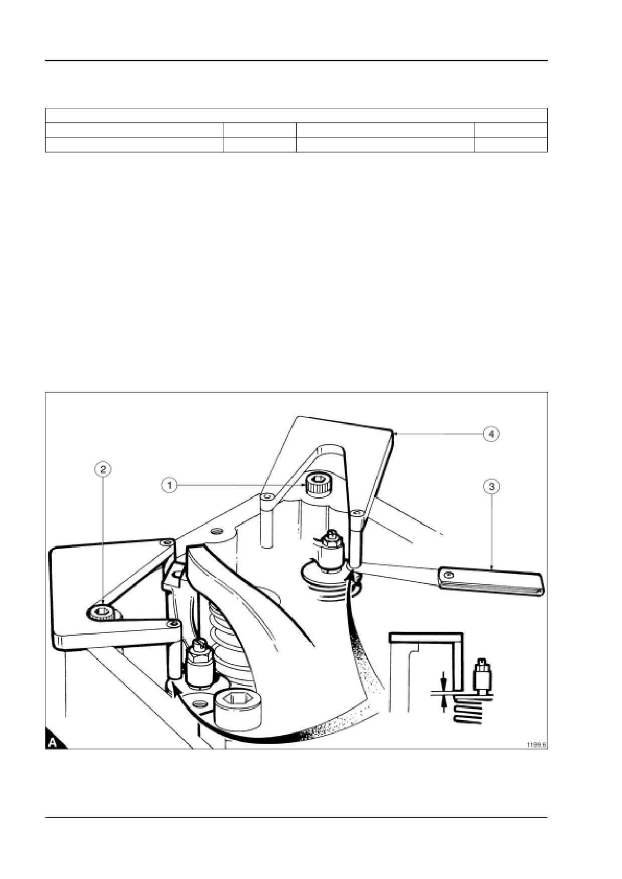
By the use of tool No. T6253/312, an indication of valve and seat wear (recession) can be obtained without the
removal of a cylinder head.
The tool is to be used as part of the bridge piece and valve clearance sequence.
Note: The inlet valves are easily checked but as there is insufficient clearance only one exhaust valve can be
checked.
1 Place the tool on the rocker box face around the bolt (A1). Position the legs of the tool above the inlet valve
spring retainers.
2 The clearance between the legs and valve spring retainers indicates the valve life left. A leg touching a valve
spring retainer indicates the need for a cylinder head overhaul.
3 To check the exhaust valve, place the tool around bolt (A2).
Note: As a result of product improvements, the rocker box to cylinder head joint has been improved using a
graphite material which is 0,7 mm thicker than the joint it has replaced. This change covers all 4016-E61TRS
engines.
To check valve seat recession on these engines use a 0,7 mm feeler gauge (A3) in conjunction with the
recession tool (A4).
40
User’s Handbook, TSL 4230, Issue 4

4016-E61TRS
5
Gas and engine fluids specification
5
Gas specification
A new engine will be set to operate on clean natural gas conforming to the British natural gas specifications
having a lower calorific value of 34,71 MJ/Sm3 (930 BTU/Sft3).
The difference between high calorific value (HCV) and low calorific (LCV) is that (HCV) is the total amount of
heat given off by the gas during combustion and the (LCV) is the high calorific value less the amount of heat
used to vaporize the water content of the gas. Since the amount of heat lost in vaporizing the water is different
for different gases, the lower calorific value of the gas is chosen as the basis for fuel consumption data. There
must be no liquid hydrocarbon fractions in the gas.
Limiting values for British Gas
Methane number must exceed
75
Combustible constituents must exceed
95%
Calorific value (LCV) to exceed
34 MJ/Nm3 (912 BTU/Sft3)
Ethane
4.5%
Hydrogen content not to exceed
0.1%
Propane must not exceed
1.0%
Isobutane content not to exceed
0.2%
Normal butane not to exceed
0.2%
Normal pentane and higher fractions (hexane, heptane, etc).
0.02%
The summation must not exceed
Minimum gas pressure at inlet to regulators
15 mbar (1.5 kPa)
Gas pressure not to exceed, without additional pressure regulators
50 mbar (5 kPa)
Hydrogen sulphide not to exceed
0.01% or 100 ppm
Note: The rating may be reduced if lower calorific value of the fuel is lower than 34,71 MJ/Nm3 (930 BTU/Sft3).
Also pressure must be constant to maintain emissions and stability. If any of the above parameters are not
met, Perkins Engines Company Limited should be consulted for advice.
Gas safety regulations
There are legal requirements that within the U.K. gas fittings and equipment must be installed only by
competent persons and in accordance with the Institution of Gas Engineers Procedures IGE UP2. Outside the
U.K. anyone undertaking work on the engine or associated with the engine and its gas equipment in particular
should check with local and national regulations to ensure compliance.
User’s Handbook, TSL 4230, Issue 4
41
5
4016-E61TRS
Lubricating oil recommendations
Approved lubricating oil
Esso Estor HPC 40
Caution: To use a lubricating oil other than that specified, it is essential that Perkins Engines Company
Limited, Stafford, is consulted, failure to do so could affect the engine warranty.
Oil and filter change programme
The lubricating oil and filter life is governed by the engine load and gas quality. To determine the optimum oil
and filter change period after the engine has been commissioned, use the oil analysis programme which
follows.
Initiating an oil analysis programme
Caution: The oil sample must be taken from the mean level in the engine sump, never from the sump drain
plug.
Note: During the engine’s initial 500 hour running period, oil analysis will show higher levels of iron and copper
than the acceptable contamination parameters, marked (*) in the list below. As the engine continues to run the
levels will drop within the specified parameters.
Every 250 hours after the first 500 hour oil and filter change the oil should be analysed.
At 750 hours by comparing the oil analysis results a contamination trend can be established, allowing each
individual operator to develop an oil and filter change policy for the operating conditions of their engine.
Caution: Irrespective of condition the lubricating oil and filters MUST be changed at 2000 hours.
Critical lubricating oil contamination parameters
Viscostatic at 100 °C
cSt max 20% above original value
Insolubles
1.5% wt.max
Total base number (TBN)
60% less than new oil value
Nitration
30 abs/cm max
Oxidation
30 abs/cm max
Water
0.2% vol max
Iron
less than 20 ppm*
Copper
less than 40 ppm*
42
User’s Handbook, TSL 4230, Issue 4
4016-E61TRS
5
Coolant specification
50% inhibited ethylene glycol or 50% inhibited propylene glycol and 50% clean fresh water.
For combined heat and power systems and where there is no likelihood of ambient temperatures below 10 °C,
then clean ‘soft’ water may be used, treated with 1% by volume of Perkins inhibitor.
The inhibitor is available under Perkins part number OE45350.
Maintenance of coolant
Warning! Always stop the engine and allow the pressurised system to cool before removing the filler cap.
Avoid skin contact with the coolant mixture.
The coolant mixture should be changed at 8,000 hours or 12 months and checked at 2,000 hour intervals for
the correct alkalinity level; the pH should not be above 7.5.
Note: A hydrometer only shows the proportion of ethylene glycol. This is not a measure of protection against
corrosion.
Caution: Failure to follow the above recommendations may result in engine damage and will invalidate the
engine warranty.
User’s Handbook, TSL 4230, Issue 4
43
This page is intentionally blank
4016-E61TRS
6
Fault diagnosis
6
Introduction
This fault diagnosis chart covers mechanical defects which may occur with the engine. It must be used in
conjunction with electronic service tools (TIPSS-EST).
To locate problems within the engine and its systems, refer to the Diagnostic Manual (TSL 4233).
Caution: Do not use mobile phones within 2 meters of the engine as the transmitted signal can affect the
electronic management system.
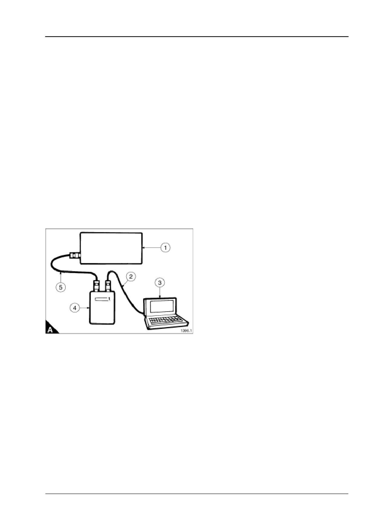
TIPSS connections (A)
A1 Engine mounted GECM box
A2 PC adaptor harness
A3 PC
A4 Interface module
A5 Service tool harness
User’s Handbook, TSL 4230, Issue 4
45

6
4016-E61TRS
Problems and possible causes
Problem
Possible causes
The starter motor turns the engine too slowly
1, 2, 3, 4
The engine does not start
5, 6, 7, 8, 10, 11, 12,
The engine is difficult to start
5, 7, 8, 9, 10, 11, 12, 26, 27, 28, 29, 46, 47
The engine is loosing power
8, 9, 10, 11, 12, 13, 15, 26, 27, 28, 29, 30, 44, 46
Misfire
7, 8, 9, 13, 15, 26, 27, 28, 29, 30
High gas consumption
7, 9, 12, 26, 27, 28, 29, 44, 46
The engine knocks
13, 20, 26, 27, 29, 30, 32, 33, 38
The engine runs erratically
7, 8, 9, 12, 26, 27, 28, 29, 30, 44, 46
Vibration
32, 33, 38, 39, 42
Low oil pressure
16, 18, 32, 33, 34, 37, 43, 48
High oil pressure
4, 35
High oil temperature
4, 13, 16, 48
Crankcase pressure
24, 29, 38
High coolant temperature
22, 23, 25, 26, 40, 41
Blue exhaust smoke
21, 24, 29, 38, 45
46
User’s Handbook, TSL 4230, Issue 4
4016-E61TRS
6
List of possible causes
1 Battery capacity low.
2 Bad electrical connections.
3 Fault in starter motor.
4 Wrong grade of lubricating oil.
5 Starter motor turns engine too slowly.
6 Ignition failed (no spark at plugs).
7 Dirty or worn spark plugs.
8 Fault in gas supply.
9 Drop in gas quality.
10
Restriction in air induction system.
11
Restricted movement of engine speed control.
12
Restriction in exhaust system.
13
Engine temperature is too high.
14
Engine temperature is too low.
15
Incorrect valve clearances.
16
Not enough lubricating oil in sump.
17
Spare.
18
Dirty lubricating oil filter element.
19
Fan damaged.
20
Fault in engine mounting or flywheel housing.
21
Too much lubricating oil in sump.
22
Restriction in air or coolant passages of radiator.
23
Electric coolant pump failure.
24
Restriction in breather.
25
Insufficient coolant in system.
26
Cylinder head flame rings leaking.
27
Worn cylinder bores.
28
Leakage between valves and seats.
29
Piston rings are seized in piston (rings worn or broken).
30
Broken valve spring.
31
Valve stems and/or guides are worn.
32
Crankshaft bearings are worn or damaged.
33
Lubricating oil pump is worn.
34
Relief valve does not close.
35
Relief valve does not open.
36
Relief valve spring is broken.
37
Fault in suction pipe of lubricating oil pump.
38
Piston is damaged.
39
Flywheel housing or flywheel is not aligned correctly.
40
Fault in thermostat or thermostat is of an incorrect type.
Continued
User’s Handbook, TSL 4230, Issue 4
47
6
4016-E61TRS
41 Restriction in coolant passages on the engine.
42 Spare.
43 Restriction in sump strainer.
44 Turbocharger impeller is damaged or dirty.
45 Lubricating oil seal of turbocharger leaks.
46 Faulty engine management system.
47 Faulty sensor.
48 Oil cooler tubestack blocked.
48
User’s Handbook, TSL 4230, Issue 4