Perkins 4000 Series Vee-Form Gas 4012 and 4016 Series Engines USER’S HANDBOOK (1998)
Perkins 4000 Series
Vee-Form Gas
4012 and 4016 Series Engines
USER’S HANDBOOK
12 and 16 cylinder turbocharged gas engines
Publication TSL4187.
The information is correct at the time of print.
Published in February 1998 by Technical Publications,
Perkins Engines Company Limited, Tixall Road, Stafford, ST16 3UB, England.
1
WARNING
READ AND UNDERSTAND ALL SAFETY PRECAUTIONS AND
WARNINGS MENTIONED IN THIS MANUAL.
IMPROPER OPERATION OR MAINTENANCE PROCEDURES
COULD RESULT IN A SERIOUS ACCIDENT OR DAMAGE TO THE
EQUIPMENT CAUSING INJURY OR DEATH.
NON-COMPLIANCE WITH THESE INSTRUCTIONS AND THOSE
INCLUDED IN THE INSTALLATION MANUAL TSL4200 MAY
INVALIDATE THE WARRANTY OFFERED WITH THE ENGINE.
MAKE QUITE CERTAIN THAT THE ENGINE CANNOT BE
STARTED IN ANY WAY BEFORE UNDERTAKING ANY
MAINTENANCE, PARTICULARLY IN THE CASE OF
AUTOMATICALLY STARTING GENERATING SETS.
4012/16 Gas, February 1998
INTRODUCTION
The purpose of this Manual is to enable the operator to carry out routine servicing of the engine.
Before undertaking any work on the engine the appropriate section in the Workshop Manual should be read
fully and completely understood prior to starting work.
The information contained within the manual is based on such information as was available at the time of going
to print. In line with Perkins Engines (Stafford) Limited policy of continual development and improvement that
information may change at any time without notice. The engine user should therefore ensure that he has the
latest information before starting work.
The instructions contained in this Manual will, provided that they are correctly carried out, ensure the safe
operation of the equipment.
Users are respectfully advised that it is their responsibility to employ competent persons to operate, maintain
and service the equipment in the interest of safety.
Certain overhaul operations are impracticable without the use of special tools, and those operators who are
not equipped to undertake major repairs are urged to consult their Perkins distributor.
When not working on the engine, ensure that all covers, blank flanges, doors, etc., are refitted to openings to
prevent the ingress of dirt, etc.
Please quote the engine type and serial number with all your enquiries. This will help us to help you. The type
and serial number are on a plate fitted to the crankcase.
If any doubt exists regarding the installation, use or application of the engine, the Installation Manual should
be consulted for further advice contact Applications Department at Perkins Engines (Stafford) Ltd.
Oil change intervals may be changed according to operating experience by agreement with Perkins Engines
(Stafford) Limited and subject to oil analysis being carried out at regular intervals.
Please note that this 4000 Series manual also covers SE engines dispatched from the factory from 1 March
1996. A table of equivalent engine designations is given on page 2.
PERKINS COMPANIES
Perkins Group of Companies
Perkins International - North America
Moteurs Perkins SA
Perkins Engines (Peterborough) Ltd.
12025 Tech Center Drive,
Parc de Reflets - Paris Nord II,
Frank Perkins Way, Eastfield,
Livonia, Michigan 48150,
165 Avenue du Bois de la Pie, BP 40064,
Peterborough, PE1 5NA, England.
U.S.A.
95913 Roissy CDG Cedex, France
Tel:
(01733) 583000
Tel:
313 266 5427
Tel:
00 33 149 90 71 72
Telex: 32501 PERKEN G
Fax: 313 266 2700
Fax: 00 33 149 90 71 90
Fax: (01733) 582240
Perkins Engines Latin America Inc
Perkins International Ltd.
Perkins Engines (Shrewsbury) Ltd.
999 Ponce de Leon Boulevard,
Varity Asia/Pacific
Lancaster Road, Shrewsbury,
Suite 710, Coral Gables,
Suite 3301, Convention Plaza,
SY1 3NX, England.
Florida 33134, U.S.A.
1 Harbour Road, Wanchai,
Tel:
(01743) 212000
Tel:
(305) 442 7413
Hong Kong.
Telex: 35171/2 PESL G
Telex:
32501 PERKEN G
Tel:
852 2588 1883
Fax: (01743) 212700
Fax: (305) 442 7419
Fax: 852 2827 2311
Perkins Engines (Stafford) Ltd.
Perkins Engines Australia Pty Ltd
Perkins Engines (Far East) Pte Ltd.
Tixall Road, Stafford, ST16 3UB, England.
Suite 2, 364 Main Street, Mornington
39 Tuas Avenue 13,
Tel:
(01785) 223141
3931, Victoria, Australia.
Singapore 638999.
Telex: 36156 PERKEN G
Tel:
(059) 75 1877
Tel:
(65) 861 1318
Fax: (01785) 215110
Telex:
30816
Fax: (65) 861 6252
Fax: (059) 75 1305
Perkins Powerpart Distribution Centre
Frank Perkins Way,
Motori Perkins SpA
Northbank Industrial Park, Irlam,
Via Socrate. 8,22070 Casnate
Manchester, M44 5PP, England.
Con Bernate (Como), Italy.
Tel:
(0161) 776 5000
Tel:
031 56 46 25 / 031 56 46 33
Specifications Help Desk
Telex:
380658 PERKIT I
Tel:
(0161) 776 5151
Fax: 031 24 90 92 / 031 56 41 45
Fax: (0161) 776 5200
Specifications Help Desk
Perkins Motoren GmbH
Tel:
(0161) 776 5100
D-63801 Kleinostheim,
Telex: 32501 PERKEN G
Saalackerstrasse 4, Germany.
Tel:
(49)
(6027) 5010
Fax: (49) (6027) 501130
In addition to the above companies, there are Perkins distributors
in
most countries. Perkins Engines
(Peterborough) Limited or one of the above companies can provide distributor handbooks Publication No. 1407/4/97.
Publication TSL4187
Published by the Technical Publications Department, Stafford.
4012/16 Gas, February 1998
1
INTRODUCTION
PERKINS ENGINES (STAFFORD)
ENGINE DESIGNATIONS
4000 SERIES AND SE SERIES
EQUIVALENT TERMS
4000 SERIES
SE SERIES
4012TESI
12SETCWG
4016TESI
16SETCWG
2
4012/16 Gas, February 1998
CONTENTS
Page
INTRODUCTION
1
ENGINE DESIGNATIONS
2
BRIEF DESCRIPTION OF THE 4012/16 GAS ENGINES
4
PHOTOGRAPHS
INSERTS
GENERAL INFORMATION
5
GAS ENGINE DATA
7
-
10
TORQUE SETTINGS
11
-
13
LUBRICATING OIL
14
-
16
COOLANT CORROSION INHIBITORS, ANTI-FREEZE
17
GAS SPECIFICATION
18
-
19
OPERATING INSTRUCTIONS
20
-
21
PREPARATION FOR INITIAL START
20
PRIMING THE TURBOCHARGER
20
BATTERIES
21
FILLING THE COOLING SYSTEM
21
INSTRUMENT PANEL (ENGINE MOUNTED)
22
-
24
EXHAUST TEMPERATURE GAUGE (OPTIONAL)
24
FINAL CHECKS AND INITIAL START UP
25
-
26
GAS ENGINE START/STOP SEQUENCE (AUTOMATIC)
27
MAINTENANCE PROCEDURES
28
-
41
OVERHAUL PERIODS & CONTINUOUS DUTY CHECKLIST
42
-
44
FAULT TRACING CHART
45
WIRING DIAGRAMS
4012/16TESI (MINNOX) WITH CAV STARTER AND PROTECTION SWITCHES
46
4012/16 (GAS) MINNOX ENGINE STARTING CIRCUIT WITH BUTEC
STARTERS AND OPTIONAL INSTRUMENT PANEL
47
EARLY 4012 SERIES GAS IGNITION AND HEINZMANN WIRING SYSTEM
48
CURRENT 4012 SERIES GAS IGNITION AND HEINZMANN WIRING SYSTEM
49
4012/16 (GAS) MINNOX ENGINE WIRING DIAGRAM OF STANDARD
PROTECTION PACK AND OPTIONAL BRITISH GAS COUNCIL
PROTECTION EQUIPMENT
50
EARLY 4016 SERIES GAS IGNITION AND HEINZMANN WIRING SYSTEM
51
CURRENT 4016 SERIES GAS IGNITION AND HEINZMAN WIRING SYSTEM
52
4012/16 LUBRICATING OIL FLOW DIAGRAM
TP315
4012/16TESI FRESH AND RAW WATER CIRCULATION DIAGRAM
TP381
(HEAT EXCHANGER COOLED)
4012TESI FRESH AND RAW WATER CIRCULATION DIAGRAM
TP384
(RADIATOR COOLED)
4012/16TESI ENGINE IGNITION AND GAS FLOW DIAGRAM
TP351
4012/16 Gas, February 1998
3
BRIEF DESCRIPTION OF THE 4012/16 GAS ENGINES
4012TESI
12 cylinder, ‘V’ form, 4 stroke, gas engine, water cooled,
(MINNOX)
turbo-charged, water cooled charge air cooler with separate water
pump and cooling circuit, lean burn, low NOx emission levels, 9.5:1
compression ratio
4012TESI
12 cylinder, ‘V’ form, 4 stroke, gas engine, water cooled,
(MINNOX)
200
L.C.
turbo-charged, water cooled charge air cooler with separate water
pump and cooling circuit, lean burn, with NOx emission of less than
200 g/GJ, 9.5:1 compression ratio.
4012TESI
12 cylinder, ‘V’ form, 4 stroke, gas engine, water cooled,
(MINNOX)
140
L.C.
turbo-charged, water cooled charge air cooler with separate water
pump and cooling circuit, lean burn, with NOx emission of less than
140 g/GJ, 9.5:1 compression ratio.
4012TESI
12 cylinder, ‘V’ form, 4 stroke, gas engine, water cooled,
(MINNOX)
140
H.C.
turbo-charged, water cooled charge air cooler with separate water
pump and cooling circuit, lean burn, with NOx emission of less than
140 g/GJ, 11.5:1 compression ratio.
4016TESI
16 cylinder, ‘V’ form, 4 stroke, gas engine, water cooled,
(MINNOX)
200
L.C.
turbo-charged, water cooled charge air cooler with separate water
pump and cooling circuit, lean burn, with NOx emission level of 200
g/GJ or less, 9.5:1 compression ratio.
4016TESI
16 cylinder, ‘V’ form, 4 stroke, gas engine, water cooled,
(MINNOX)
140
L.C.
turbo-charged, water cooled charge air cooler with separate water
pump and cooling circuit, lean burn, with NOx emission of 140 g/
GJ or less, 9.5:1 compression ratio.
4016TESI
16 cylinder, ‘V’ form, 4 stroke, gas engine, water cooled,
(MINNOX)
140
H.C.
turbo-charged, water cooled charge air cooler with separate water
pump and cooling circuit, lean burn, with NOx emission of 140 g/
GJ or less, 11.5:1 compression ratio.
4016TESI
16 cylinder, ‘V’ form, 4 stroke, gas engine, water cooled,
(MINNOX)
90 H.C.
turbo-charged, water cooled charge air cooler with separate water
pump and cooling circuit, lean burn, with NOx emission of 90 g/GJ
or less, 11.5:1 compression ratio.
4
4012/16 Gas, February 1998
4012TESI (MINNOX)
4012TESI (MINNOX)
4016TESI (MINNOX)
4016TESI (MINNOX)
GENERAL INFORMATION
SAFETY
Engine lift equipment
Use only the lift equipment which is designed
for the engine.
Use lift equipment or obtain assistance to lift
heavy engine components such as the
cylinder block, cylinder head, flywheel
housing, crankshaft and flywheel.
Check the engine lift brackets for security
before the engine is lifted.
Fig. 1
Asbestos joints
The following is a list of 'Health Protection
Some joints and gaskets contain
Precautions', suggested to minimise the risk
compressed asbestos fibres see Warning
of contamination.
label Fig. 1 in a rubber compound or in a
metal outer cover. The 'white' asbestos
1.
Avoid prolonged and repeated contact
(Chrysotile) which is used is a safer type of
with used engine oils.
asbestos and the danger of damage to
2.
Wear protective clothing, including
health is extremely small.
impervious gloves where applicable.
Contact with asbestos particles normally
3.
Do not put oily rags into pockets.
occurs at joint edges or where a joint is
4.
Avoid contaminating clothes, particularly
damaged during removal, or where a joint is
underwear, with oil.
removed by an abrasive method.
5.
Overalls must be cleaned regularly.
To ensure that the risk is kept to a minimum,
Discard unwashable clothing and oil
the procedures given below must be
impregnated footwear.
followed when an engine which has
6.
First aid treatment should be obtained
asbestos joints is dismantled or assembled.
immediately for open cuts and wounds.
● Work in an area with good ventilation.
7.
Apply barrier creams before each period
● Do NOT smoke.
of work to aid the removal of mineral oil
● Use a hand scraper to remove the joints
from the skin.
- do NOT use a rotary wire brush.
8.
Wash with soap and hot water, or
● Ensure that the joint to be removed is
alternatively use a skin cleanser and a
wet with oil or water to contain any loose
nail brush, to ensure that all oil is
particles.
removed from the skin. Preparations
● Spray all asbestos debris with water and
containing lanolin will help replace the
place it in a closed container which can
natural skin oils which have been
be sealed for safe disposal.
removed.
9.
Do NOT use petrol, kerosene, diesel
fuel, gas oil, thinners or solvents for
Dangers from used engine oils
washing the skin.
Prolonged and repeated contact with mineral
10.
If skin disorder appears, medical advice
oil will result in the removal of natural oils
must be taken.
from the skin, leading to dryness, irritation
and dermatitis.
The oil also contains
11.
Degrease components before handling
potentially harmful contaminants which may
if practicable.
result in skin cancer.
12.
Where there is the possibility of a risk to
Adequate means of skin protection and
the eyes, goggles or a face shield
washing facilities should be readily available.
should be worn. An eye wash facility
should be readily available.
4012/16 Gas, February 1998
5
GENERAL INFORMATION
Environmental protection
Practical Information
There is legislation to protect the
To clean components
environment from the incorrect disposal of
It is important that the work area is kept clean
used lubricating oil. To ensure that the
and that the components are protected from
environment is protected, consult your Local
dirt and debris. Ensure that dirt does not
Authority who can give advice.
contaminate the fuel system.
Before a component is removed from the
engine, clean around the component and
Viton seals
ensure that all openings, disconnected
Some seals used in engines and in
hoses and pipes are sealed.
components fitted to engines are made from
Remove, clean and inspect each component
Viton.
carefully. If it is usable, put it in a clean dry
Viton is used by many manufacturers and is
place until needed. Ball and roller bearings
a safe material under normal conditions of
must be cleaned thoroughly and inspected. If
operation.
the bearings are usable, they must be
If Viton is burned, a product of this burnt
flushed in low viscosity oil and protected with
material is an acid which is extremely
clean paper until needed.
dangerous. Never allow this burnt material
Before the components are assembled,
to come into contact with the skin or with the
ensure that the area is free from dust and dirt
eyes.
as possible. Inspect each component
If it is necessary to come into contact with
immediately before it is fitted, wash all pipes
components which have been burnt, ensure
and ports and pass dry compressed air
that the precautions which follow are used:
through them before connections are made.
● Ensure that the components have
Use suitable gloves for protection when
cooled.
components are degreased or cleaned with
● Use Neoprene gloves and discard the
trichloroethylene,
white
spirit,
etc.
gloves safely after use.
Degreasing solutions which are basically
● Wash the area with a calcium hydroxide
trichloroethane are not recommended.
solution and then with clean water.
● Disposal of gloves and components
which are contaminated, must be in
accordance with local regulations.
If there is contamination of the skin or eyes,
wash the affected area with a continuous
supply of clean water or with a calcium
hydroxide solution for 15-60 minutes. Obtain
immediate medical attention.
6
4012/16 Gas, February 1998
GAS ENGINE DATA
The figures quoted are based on engines set to meet the ISO 3046/1 1981 Condition.
For full technical data please refer to the Product Information Manual.
Type (Gas) 12 cylinder and 16 cylinder (MINNOX) 'V' form, water cooled, turbocharged, wet
exhaust manifolds with separate raw water cooled charge air cooler.
RANGE
4012TESI (MINNOX)
4016TESI (MINNOX)
Cycle
4 stroke
Configuration
‘V’ form
Bore
160 mm
Stroke
190 mm
Total swept volume
45.842 litres
61.123 litres
Compression ratio
9.5:1 or 11.5:1
Rotation
Anti-clockwise looking on flywheel end
1A,6B,5A,2B,3A,4B
1A,1B,3A,3B,7A,7B,5A,5B
Firing order
6A,1B,2A,5B,4A,3B
8A,8B,6A,6B,2A,2B,4A,4B
Cylinder numbering
Cylinder 1 furthest from flywheel
Cylinders designated A are on the left side of the engine when viewed from opposite end to the flywheel, with
cylinders designated B on the right hand side of the engine.
NOTE: This is NOT the same as the British Standard and ISO designation.
Valve clearances
Exhaust 0.4 mm (0.016”)
Valve dia (mm) inlet & exhaust
48
Valve timing
See Workshop Manual Section U7
Valve setting
See page 39 onwards
Ignition timing
See engine number plate
Piston speeds
Engine r/min
m/s (ft/min)
1000
6.33
(1247)
1200
7.60
(1496)
1500
9.50
(1870)
TYPICAL COOLING SYSTEM
Approved coolants
See page 17
Total capacity engine including
charge air cooler & wet exhaust
81 litres (17.8 gals)
110 litres (24.3 gals)
manifolds
Total capacity engine and radiator
239 litres (52.6 gals)
278 litres (61.3 gals)
Total capacity engine and heat
153 litres (33.7 gals)
183 litres (40.3 gals)
exchanger
Engine shut down temperature
96°C
To be determined from heat dissipated and water flow through each
Max. temperature into engine
particular engine model
Thermostat opening temperature
71°C (nat. gas) 85°C (landfill or biogas) 92°C (HC engines)
System pressure
0.5 - 0.7 bar
Maximum pressure at jacket
2.5 bar max
coolant pump outlet
4012/16 Gas, February 1998
7
GAS ENGINE DATA
GAS SYSTEM
4012TESI (MINNOX)
4016TESI (MINNOX)
Approved gas
British Natural Gas
Lower calorific value
34.71 MJ/nm3
Carburettor mixing unit
Deltec 200 - 11
Carburettor throttle body
Deltec 100 - 11
Deltec 140 - 11
Gas control valve
Deltec 36 mm dia.
Deltec 45 mm dia.
Deltec 38 mm dia. 4016TESI (minnox 140 HE) ONLY
Gas pressure min.
15 m bar (1.5 kPa)
Gas pressure max.
50 m bar (5 kPa)
Regulator type (Zero pressure)
Dungs FRS 220, 5065 or 5100
Later engines
or Kromschroder GI50 R02 or GI65 R02
If above 50 mbar (5kPa), an additional regulator should be used in
Supply pressure
order to bring the supply pressure to between the max. & min.
figures given above
Additional items to meet The Instituion of Gas Engineers procedures IGE/UP/3 for 4012/16 (Minnox)
Perkins Part No. (see Spares Book)
Low pressure detector
(low pressure gas supply only)
Gas solenoid valves
Not Perkins supply
Spit back detector
Perkins Part No. (see Spares Book)
Manual gas shut-off valve
Perkins Part No. (see Spares Book) (if fitted)
IGNITION SYSTEM
Ignition unit type
Altronic DISN 800
Ignition coil type
Altronic 501 061 (L.C. engines) Altronic 591 010 (H.C. engines)
CHAMPION RN79G 14mm (earlier L.C. engines)
Spark plug type
CHAMPION RB77 WPC 18mm (later engines)
RN79G 0.5 mm (0.020”)
Spark plug gap
RB77WPC 0.4 mm (0.015”)
GOVERNOR
Make
Heinzmann Electronic
Type
2 x E6V
2 x E10
LUBRICATION SYSTEM
Recommended oil
See pages 14 - 16
Type of system
Wet sump, external mounted oil pump
Total oil capacity (oil cooler and filter)
178 litres (39 gals)
238 litres (51 gals)
Sump capacity (dipstick) min.
136 litres (30 gals)
147 litres (32 gals)
Sump capacity (dipstick) max.
159 litres (35 gals)
214 litres (47 gals)
Min. oil pressure (rated speed) to bearings
340 kPa (49 lb/in2)
Crankcase pressure max
25 mm water gauge
Max. oil temperature in sump
105°C
Lubricating oil filter
disposable canister type
Crankcase breather
Closed circuit
8
4012/16 Gas, February 1998

GAS ENGINE DATA
INDUCTION SYSTEM
4012TESI (MINNOX)
4016TESI (MINNOX)
Air cleaner
Twin
Type (paper element)
S551A
Max. air intake depression
543 mm H2O (40 mm Hg) (L.C. engines)
406 mm H2O (30 mm Hg) (H.C. engines)
Air restriction Indicator setting
380 mm H2O
Twin Garrett (4016TESI 140 H.C. only)
Turbocharger
Twin Schwitzer (all other engines)
EXHAUST SYSTEM
Manifold type
WET
Exhaust outlet flange
Vertical (twin)
Mating flange
2 x 6” Table D
Max. exhaust back pressure
40 mm Hg
Max. exhaust temperature (°C)
See Product Information Manual
(after turbocharger)
FLYWHEEL
SAE Size
18”
No. of teeth on ring gear
156
FLYWHEEL HOUSING
SAE Size
‘00’
CRANKSHAFT
Maximum overhung weight on rear
1700 Kg
bearing
T.V. damper
1 x 18”
2 x 20”
NOTE: Subject to torsional vibration investigation different T.V. dampers may be fitted.
DRY WEIGHT
Dry weight
4380 kg
5520 kg
Wet weight
4680 kg
5820 kg
HOLDING DOWN BOLT HOLES
Bolt size (engine feet)
22 mm
No. off
8
ELECTRICAL SYSTEM
Voltage
24
Alternator type
Prestolite LNA4024/5 with internal regulator
Alternator output (amps)
30 at a stabilised output of 28 volts
Starter motor type (Twin) Prestolite/Butec
MS1/108
MS7/5
No. of teeth (gear ring)
156
No. of teeth (starter motor)
12
Battery capacity cold cranking amps
286
(each battery)
286
(each battery)
to IEC Standard at 0°C (32 °F)
Battery (lead acid)
24 V (2 x 12 V) at 0°C (32 °F) (286 Ah)
4012/16 Gas, February 1998
9
GAS ENGINE DATA
PROTECTION EQUIPMENT
Before resetting protection equipment, it must be established whether special settings (for that individual
engine) have been specified in the engine sales contract. This is particularly important with ALL high water
temperature settings, and ALL Cogen applications.
Standard settings for protection equipment are as follows:
High air manifold pressure switch
172 kPa (25.1 lb/in2)
Shutdown switches
Alarm
Shutdown
High oil temperature
115°C
120°C
Low oil pressure
2.06 bar (30 lb/in²)
1.93 bar (28 lb/in²)
High water temperature
71°C Thermostat
91°C
96°C
85°C Thermostat
96°C
101°C
96°C Thermostat
100°C
105°C
Caution: The above standard settings do not supercede any settings specified in the engine sales contract.
Overspeed
15% (on 1500 rev/min only)
High air manifold bursting disc pressure
75 lb/in² at 42°C or 58 lb/in² at 120°C
(Early engines only)
AIR STARTING
Air Starter Pressure
150 lb/in² (1034 kPa)
Compressed air supply
170 lb/in² (1172 kPa)
Type
Ingersoll-Rand Type SS815
INSTRUMENT PANEL (ENGINE MOUNTED)
Normal operation
Oil pressure
Between 300 - 560 kPa (42.6 - 80 lb/in²)
Oil temperature
Between 80 - 90 °C (176 - 194 °F)
Water temperature
Between 65 - 85 °C (149 - 185 °F)
Exhaust temperature
See Product Information Manual
Boost pressure
See Test Certificate
COOLANT JACKET HEATING
Heater
2 x 4 kw
10
4012/16 Gas, February 1998
TORQUE SETTINGS
IT IS ESSENTIAL THAT THE CORRECT LENGTH OF SCREW OR
WARNING
BOLT IS USED. INSUFFICIENT THREAD MAY RESULT IN THE
THREAD BEING STRIPPED. WHEREAS TOO LONG A THREAD MAY RESULT IN
BOTTOMING IN A BLIND HOLE, OR CATCHING ON ADJACENT COMPONENTS.
NOTE:
* Bolt and threads must be lubricated with clean engine oil.
** Cylinder head bolts to be lubricated under the heads, under the washers and
on the threads with P.B.C. (Poly-Butyl-Cuprysil) grease. Important:
See Section R10 in
the Workshop Manual before fitting. All other bolt threads only to be lubricated with clean
engine oil. Care must be taken not to oil the heads and faces.
TORQUE SETTINGS
CYLINDER HEAD GROUP
Ibf.ft
Nm
** Cylinder head bolt (early type)
M24
550
750
See Section R14
** Cylinder head bolt (later (waisted) type)
M24
530
723
Rocker shaft bolt/nut
M16
90
120
Rocker adjuster nut inlet/exhaust
M12
35
50
Rocker box bolt
M10
35
50
Air manifold bolt
M10
35
50
Exhaust manifold bolt
M10
50
70
Turbocharger V-band clamp nuts - (Schwitzer)
7
9.5
(Mitsubishi)
7
9.5
(Garrett)
10
13.5
Sandwich plate retaining capscrew (if fitted)
M10
40
57
CRANKCASE AND CRANKSHAFT GROUPS
* Main bearing bolt
M24
580
783
Side bolts (main bearing caps)
M16
124
168
Bolts sump to crankcase
M10
40
57
* Connecting rod bolt
M16
210
285
Viscous damper bolts to crankshaft
M16
250
340
Flywheel bolt to crankshaft
M16
250
340
Front drive adaptor bolts to crankshaft
M16
250
340
Balance weight bolt
M16
250
340
Front crankshaft pulley bolt
M16
250
340
Piston cooling jet setscrew
M10
35
50
Flywheel housing bolt
M10
35
50
LUBRICATING OIL PUMP
Bolts, pump housing to gearcase plate
M10
35
50
Thin nut gear to drive shaft
M24
175
237
4012/16 Gas, February 1998
11
TORQUE SETTINGS
Ibf.ft
Nm
CAMSHAFT GROUP
Camshaft gear bolt
M12
110
150
Camshaft thrust plate bolt
M10
35
50
Camshaft follower housing capscrew
M10
50
70
Cam follower housing bolt
M10
35
50
Idler gear hub bolts
M10
35
50
WATER PUMP AND OIL PUMP GROUPS
Water pump/oil pump gear units
M24
170
230
Water header to oil cooler bolts
M10
35
50
Water header to gearcase bolts
M10
35
50
Raw water pump gear securing nut (non lubricated thread)
M35
184
250
Engine Feet
M12
70
95
GOVERNOR
Control shaft mounting plate bolt
M10
35
50
FAN DRIVE
Fan driven pulley taper lock bush screw
1/2" BSW
35
50
5/8" BSW
124
170
ALTERNATOR
Drive pulley taper lock bush screws
3/8" BSW
14
20
IGNITION SYSTEM
Spark plug
M18 x 1.5
35
50
Adaptor clamp capscrew
M12
100
136
Adaptor clamp screw (earlier engines)
M10
50
68
Retaining bolt for timing disc cover
M10
35
50
Timing disc housing to mounting plate bolt
M10
35
50
Drive gear screw
M10
50
70
Drive coupling capscrew
M6
10
13.5
Driven gear capscrew
M10
50
70
Magnet disc to shaft nut
M12
35
50
Disc shaft flange to camshaft bolt
M12
120
171
FLEXIBLE COUPLING (HOLSET)
Flexible coupling cover screw
M12 or1/2" UNC
90
129
Coupling driving flange screws
(coupling size
2.15)
M12 or1/2" UNC
90
129
to flywheel
(coupling size
3.86)
M16 or5/8" UNC
175
250
12
4012/16 Gas, February 1998
TORQUE SETTINGS
GENERAL TORQUE LOADINGS
The following torque loadings are general for metric coarse threads for grade 8.8 steel and
do not supersede the figures quoted above.
Thread Size (mm)
Ibf.ft
Nm
8
18
25
10
35
50
M10-12.9 steel
50
70
These are based to BS 3692.
4012/16 Gas, February 1998
13
LUBRICATING OIL
QUANTITY OF OIL
4012TESI
4016TESI
The total system capacity
178 litres (39 gallons)
238 litres (52 gallons)
The maximum sump capacity
159 litres (35 gallons)
214 litres (47 gallons)
The minimum dipstick mark indicates
136 litres (30 gallons)
147 litres (32 gallons)
CAUTION
In order to select a suitable lubricating oil for a gas engine it is necessary to consider
the fuel quality.
NATURAL GAS ENGINES (NO ACIDIC PRODUCTS PRESENT)
The oil should be a grade that is specifically formulated by all the major oil companies for
turbocharged and charge cooled natural gas engines. The oil should contain anti-wear and
detergent/dispersant additives. The oil is to have high resistance to oxidation and have
good thermal stability. Modern gas engine oils do not rely on a high total base number to
achieve long life and the special additive packages that are now available from many of the
major oil suppliers now meet this criteria.
Engines fitted with oxidizing catalysts (2 way) require a lubricant that is low in zinc and
phosphorus, it is essential that the oil supplier confirms that the brand of oil supplied is
compatible with the catalyst.
BIOGAS ENGINES (CONTAINING ACIDIC PRODUCTS AT LEVELS APPROVED BY
PERKINS ENGINES (STAFFORD) LTD
These engine require a lubricating oil that has more reserve alkalinity than the natural gas
engine and therefore the TBN should be more than 8 and less than 10 with the sulphated
ash in the range of 0.5 to 1.1%. The oil supplier will assist with the selection of suitable oils
when presented with the gas analysis. (TBN = Total Base Number).
NATURAL GAS BIOGAS ENGINES
Where gas engines oils are not available, please consult Perkins Engines (Stafford) Ltd for
advice.
GRADE OF OIL
The viscosity of the oil used should be either SAE 30 or SAE 40. In general SAE 30 is used
at temperature less than 30°C average ambient temperature and SAE 40 more than 30°C.
As these engine are generally operating continuously, it is possible to use higher viscosity
oils as sluggishness in starting is not generally critical.
The use of SAE40 will give reduced oil consumption but under certain conditions it will also
give reduced oil change periods.
OIL CHANGE PERIOD (NATURAL GAS ENGINES)
For normal operation of gas engines, change the oil after the first 500 hours, after which the
oil change period is 800 hours or annually which ever is the sooner.
It may be possible to extend the oil change period, where an oil change programme has
been approved by Perkins Engines (Stafford) Ltd, based upon the analysis of oil samples
taken during the first 1000 hours of engine use. However even if an analysis is showing a
satisfactory oil quality, the oil life should not be extended above 1000 hours.
14
4012/16 Gas, February 1998
LUBRICATING OIL
The following should be regarded as critical parameters:
Viscosity at 100°C
16.5 cSt maximum
Insolubles
1.5 maximum
Total Acid Number (TAN)
less than 4 times the TAN value for new oil.
Total Base Number (TBN)
50% less than new oil value.
Total base number (TBN) and total acid number (TAN) must not cross over.
Nitration
25 maximum
Oxidation
25 maximum
Water
0.2% maximum
Iron
Less than 20ppm*
Copper
Less than 40ppm*
NB Oil samples should be taken from the mean level in the engine sump never from the
sump drain plug.
Should there be a lubricating oil supply problem or a high sulphur content in the gas, Perkins
Engines (Stafford) Ltd should be contacted to give advice in selecting suitable formulations.
OIL CHANGE PERIOD (BIOGAS ENGINES)
Engines that are operated on either digester gas or landfill gas are to be subjected to special
conditions regarding the oil change periods.
When the engine/s are first commissioned an analysis of the site gas is to be submitted to
Perkins Engines (Stafford) (this is addition to the analysis supplied at the order stage) and
a description of the proposed lubricating oil that is to be used.
When the engine starts operating it is essential that oil samples are taken at intervals of
every 150 hours with the result of the analysis being sent to Perkins Engines (Stafford) at
the earliest opportunity.
This course of action is necessary because of the variability of the gas. If the oil is allowed
to be used after it has deteriorated beyond the limits specified below then the engine may
be damaged. The warranty on the engine is dependant on the oil being maintained in
satisfactory condition. To meet this requirement it is necessary to continue the oil analysis
programme throughout the warranty period. The frequency of the analysis can be extended
but it must show that at the oil change point that the oil is still in acceptable limits.
CRITICAL PARAMETERS
Maximum viscosity at 100°C
16.5 cSt
Total acid number and total base number must not cross over
TBN must not reduce to less than 50% the value of new oil
Nitration must not exceed
25
Oxidation must not exceed
30
Insolubles >3 µ must not exceed
1.5
Water max %
0.2
Silicon max ppm
100
Sodium max ppm
50
Iron max ppm
35*
Copper max ppm
35*
4012/16 Gas, February 1998
15
LUBRICATING OIL
During the early life of the engine it will be found that the parameters marked * will have
higher levels as a result of the running in procedure.
UNDER NO CIRCUMSTANCES IS THE OIL TO BE USED FOR MORE THAN 900 HOURS
EVEN IF THE ANALYSIS SHOWS THAT THE OIL IS IN ACCEPTABLE CONDITION.
NOTE: When operating on methane based fuels, approximately one litre of water is
produced for every cubic metre of methane burnt. It is essential to ensure that the piston
blow by can not condense either in the crankcase or in any pipes associated with the
breather. Water has a devastating effect on oil life due to the attack on the additive package
in the oil. It is essential that the engine breather is functioning effectively. Water should be
drained from the sump weekly.
FAILURE TO COMPLY WITH THESE INSTRUCTIONS MAY
WARNING
RESULT IN ENGINE DAMAGE.
APPROVED LUBRICATING OILS (NATURAL GAS ENGINES)
(Suitable for British and Durch natural gas)
Oil Company
Type
MOBIL
Pegasus 480 (Suitable for catalyst equipped engines)
MOBIL
Pegasus 489
ESSO
Estor Supreme LA 40
ESSO
Estor Protec LA 40
TEXACO
Geotex LA or HD
SHELL
Mysella MA 40
CASTROL
NG404-408
APPROVED LUBRICATING OILS (BIOGAS AND OTHER GASES)
Oil Company
Type
MOBIL
Pegasus 489 + *EM/PA programme
*EM/PA = Equipment Maintenance through Progressive Analysis
CATALYST EQUIPPED GAS ENGINES
These require oils with sulphated ash limited to
0.5%, zinc limited to
0.04%
and
phosphorous limited to 0.09% by weight, (see the above table).
16
4012/16 Gas, February 1998
COOLANT
When mixing the anti-freeze with the water
ALWAYS STOP
WARNING
always
follow
the
manufacturer's
THE ENGINE AND
recommendation which is to add the anti-
ALLOW THE PRESSURISED SYSTEM
freeze to water and mix thoroughly before
TO COOL BEFORE REMOVING THE
adding the mixture to the engine cooling
FILLER CAP. AVOID SKIN CONTACT
system.
WITH ANTIFREEZE BY WEARING
Mixing water to the anti-freeze can lead to
HAND PROTECTION.
the formation of gel in the mixture, due to
over concentration, and this can lead to
ENGINE COOLING SYSTEM
blockage of water passages and subsequent
To protect the engine cooling system against
loss of water flow causing overheating.
corrosion it is essential that the engine
coolant contains suitable additives which will
MAINTENANCE OF COOLANT
give the necessary protection.
The water/anti-freeze mixture should be
Caution: untreated water is not suitable.
replaced in operating engines at least once a
year.
WATER QUALITY
It is essential to maintain the coolant at the
The water that is mixed with the additive
correct alkalinity level i.e. the pH should not
must have the following characteristics:
increase above
7.5. A hydrometer only
Chloride less than
80 PPMV (parts per
shows the proportion of ethylene glycol.
million by volume)
This is not a measure of protection
Sulphates less than 80 PPMV
against corrosion.
Total hardness less than 200 PPMV pH of
water between 7 to 7.5 (i.e. neutral to slightly
FAILURE TO
alkaline)
WARNING
FOLLOW THE
ABOVE RECOMMENDATIONS MAY
ADDITIVES TO WATER
RESULT IN ENGINE DAMAGE AND
Due to the complexity of the cooling system
WILL INVALIDATE THE ENGINE
it is necessary to use an additive that
contains a balanced package of corrosion
inhibitors.
To achieve the required solution a 50/50 mix
of Shell Safe Premium anti-freeze with water
should be used at all times, even in areas
where frost is unlikely.
This mixture will give frost protection down to
-35°C. In areas where Shell anti-freeze is
unobtainable contact Perkins Engines
(Stafford) Ltd for advice.
Under no circumstances should an additive
containing nitrites, borates, phosphates,
chromates, nitrates or silicates be used, as
these materials are not compatible with the
materials used in the cooling system.
4012/16 Gas, February 1998
17
GAS SPECIFICATION
A new engine will be set to operate on clean natural gas conforming to the British natural
gas specifications having a lower calorific value of 34.71 MJ/Sm³ (930 BTU/Sft³).
The difference between high calorific value (HCV) and low calorific value (LCV) is that (HCV)
is the total amount of heat given off by the gas during combustion and the (LCV) is the high
calorific value less the amount of heat used to vaporize the water content of the gas. Since
the amount of heat lost in vaporizing the water is different for different gases, the lower
calorific value of the gas is chosen as the basis for fuel consumption data. There must be
no liquid hydrocarbon fractions in the gas.
IF THE ENGINE IS NOT SET TO SUIT THE SITE GAS,
WARNING
UNECONOMICAL RUNNING, LOSS OF POWER OR DAMAGE
MAY OCCUR, WHICH COULD RESULT IN INJURY.
Where gases other than British Natural Gas are to be used, such as wellhead gas, digester
gas and landfill gas, it is essential that a detailed analysis of the gas is submitted to Perkins
Engines (Stafford) Ltd. as resetting or changing the standard gas equipment may be
necessary.
Limiting Values for British Natural Gas:
4012/16TESI (MINNOX)
200 &140 L.C.
140 & 90 H. C.
1)
Methane number must exceed
65
80
2)
Combustible constituents must exceed
85%
95%
3)
Calorific value (LHV) to exceed
31.7 MJ/Nm3
34 MJ/Nm3
(850 BTU/Sf3)
(912 BTU/Sft3)
4)
Ethane
6%
4.5%
5)
Hydrogen content not to exceed
0.2%
0.1%
6)
Propane must not exceed
2%
1%
7)
Isobutane content not to exceed
0.2%
0.2%
8)
Normal butane not to exceed
0.2%
0.2%
9)
Normal pentane and higher fractions
(hexane, heptane, etc.).
The summation must not exceed.
0.02%
0.02%
10) Gas pressure at inlet to regulators
15 mbar
15 mbar
must exceed
(1.5 kPa)
(1.5 kPa)
11) Gas pressure not to exceed without
50 mbar
50 mbar
additional pressure regulators
(5 kPa)
(5 kPa)
12) Hydrogen sulphide not to exceed
0.01%
0.01%
or 100 ppm
or 100 ppm
NOTE: The rating may be reduced if lower calorific value of the fuel is lower than 34.71 MJ/
Nm³ (930 BTU/Sft³). Also pressure must be constant to maintain emissions and stability. If
any of the above parameters are not met, Perkins Engines (Stafford) Ltd should be
consulted for advice.
GAS SAFETY REGULATIONS
There are legal requirements that within the U.K. gas fittings and equipment are installed
and used in accordance with the GAS SAFETY
(INSTALLATION AND USE)
REGULATIONS. Only competent persons should install this equipment. Reference should
be made to the Institute of gas engineers IGE UP/3. Outside the UK anyone undertaking
work on the engine or associated with the engine and its gas equipment in particular should
check with local and national regulations to ensure compliance.
18
4012/16 Gas, February 1998
GAS SPECIFICATION
DERATING
IT IS ESSENTIAL
WARNING
THAT FULL
ACCOUNT IS TAKEN OF ALL DERATING
INFLUENCES WHETHER GAS
SPECIFICATION, ALTITUDE, AMBIENT
TEMPERATURE OR HUMIDITY. WHERE
ANY OF THESE DEVIATE FROM THE
STANDARD SPECIFIED IN THIS
MANUAL THE RATING OF THE GAS
ENGINE MUST BE ADJUSTED AS
INSTRUCTED BELOW.
SETTING ENGINE POWER TO SUIT
ACTUAL SITE CONDITIONS
Derating means reducing the power output
of an engine from its normal rating at normal
temperature and pressure conditions to
allow for adverse effects of site conditions
e.g. altitude and ambient temperature.
Perkins Engines
(Stafford) Ltd. may be
unaware of the final destination of an engine
at the time of despatch from the works. The
engine will be set to give the power output at
normal temperature and pressure under ISO
3046
standard conditions, using gas
conforming to British Natural Gas
Specification, having a lower calorific value
of 34.71 MJ/Nm³ (930 BTU/Sft³), which when
operating under the actual site conditions,
could result in severe damage to the engine
(refer to page 18).
Providing that the actual gas being used
meets with the above conditions, then the
engine need only be derated for altitude and
ambient temperature conditions.
Any engine so supplied must be derated in
accordance with the published percentage
derate figure as shown in the Product
Information manual, by the Equipment
Manufacturer on his premises, or even on
site.
To derate, calculate,
(using the above
percentage derate figure) the new reduced
power output of the engine, and run the
engine or generating set on this load.
Where possible this maximum load limit
should be set and locked in the engine
control panel.
4012/16 Gas, February 1998
19
OPERATING INSTRUCTIONS
PREPARATION FOR INITIAL START
FILLING THE ENGINE WITH OIL
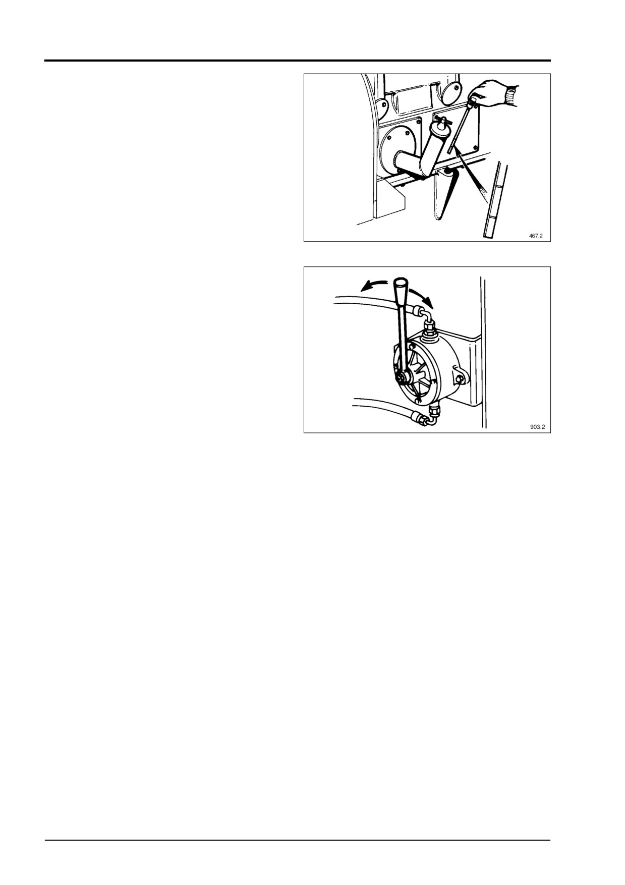
Remove the drain plug to ensure sump is
clean and empty, refit and tighten the plug.
Remove the oil filler plug situated on the left
hand side of the gearcase by rotating T-bar
anti-clockwise and pulling Fig.
2. Fill the
sump to maximum mark on the dipstick with
the appropriate grade and quality of oil
specified, see Pages 14 - 16 and replace the
plug, rotating the T-bar to tighten and seal it.
Fig.
2
PRIMING THE TURBOCHARGER
Before starting the engine for the first time, or
if it has been stood idle for more than three
months, the turbocharger bearings should
be primed. Ensure that the gas supply is
turned off, also the switch in the control panel
is in the stop position, and the ignition is
turned off.
Locate the semi-rotary hand pump which
may be found immediately in front of the oil
pump (see Fig. 3). Operating the pump
coveys oil from the sump via a one way valve
Fig.
3
to the crankcase, pressurising the lubricating
system through the oil filters. Pump until
approximately 35 kPa (5lb/in²) is indicated
on the oil pressure gauge. Continue
pumping for a further 20 seconds to ensure
that oil has reached the turbocharger.
20
4012/16 Gas, February 1998
OPERATING INSTRUCTIONS
BATTERIES (PERKINS BATTERIES ARE
SUPPLIED DRY CHARGED. SEE
INSTALLATION MANUAL TSL4200)
HAND PROTECTION
WARNING
MUST BE WORN
WHEN CHECKING ELECTROLYTE
LEVELIN THE BATTERY. INFLAMMABLE
GAS IS GIVEN OFF BY THE BATTERY.
DO NOT CHECK WITH A NAKED FLAME.
Fig. 4
Check the level of electrolyte in each of the
battery cells; it should be 8-16 mm above the
After installation and before the first start
plates. Using a hydrometer, check that the
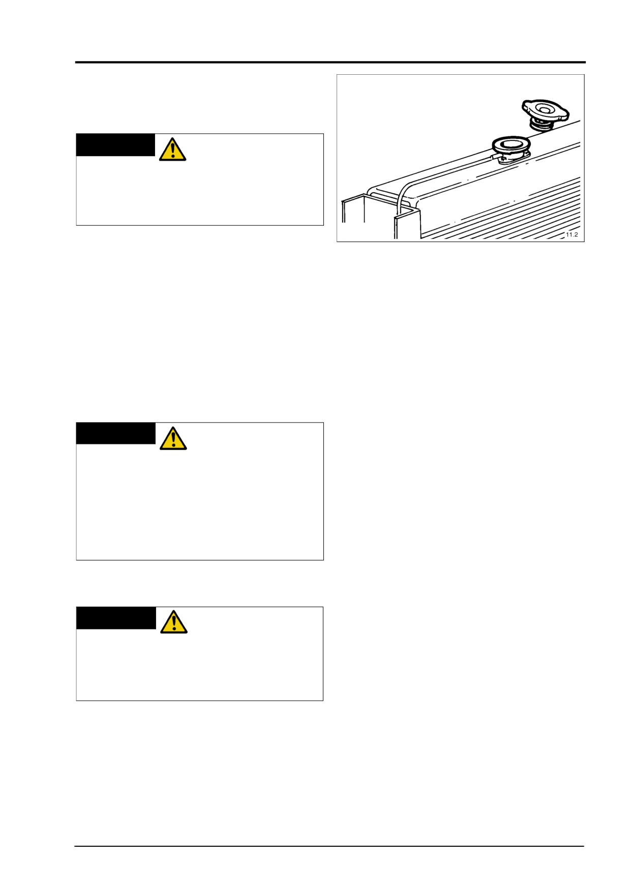
remove the radiator cap Fig. 4 by rotating it
batteries are fully charged. A fully charged
anti-clockwise. Fill the cooling system with
battery will have a specific gravity of 1.27 to
the required coolant. Should the engine be
1.285, assuming the air temperature is
fitted with water cooled exhaust manifolds
below 32°C. For higher temperatures the
then these may need bleeding
(see
specific gravity will be 1.24 to 1.255. When
Workshop Manual Section F7). Run the
topping up the batteries always use pure
engine off-load for one minute to ensure that
distilled water and always replace the plugs
the system is completely filled, then stop the
after filling.
engine and top up the system to 25 mm (1")
below the top of the filter neck then replace
the cap.
NEVER CONNECT
WARNING
A BATTERY INTO
THE SYSTEM WITHOUT FIRST
CHECKING THE POLARITY AND
VOLTAGE.
NEVER DISCONNECT THE BATTERY
WHILST THE ENGINE IS RUNNING.
NEVER FLASH CONNECTIONS TO
CHECK FOR CURRENT FLOW.
FILLING THE COOLING SYSTEM
THE COOLING
WARNING
SYSTEM IS
PRESSURISED - DO NOT REMOVE THE
FILLER CAP FROM THE RADIATOR
WHILST THE ENGINE IS HOT. HAND
PROTECTION MUST BE WORN.
The use of plain drinking water is not
recommended owing to chemical reactions
which can result in corrosion and furring-up
of the cooling system. A solution of either
water and universal anti-freeze or water and
corrosion preventative must be used. Refer
to page 17.
4012/16 Gas, February 1998
21
INSTRUMENT PANEL (ENGINE MOUNTED)
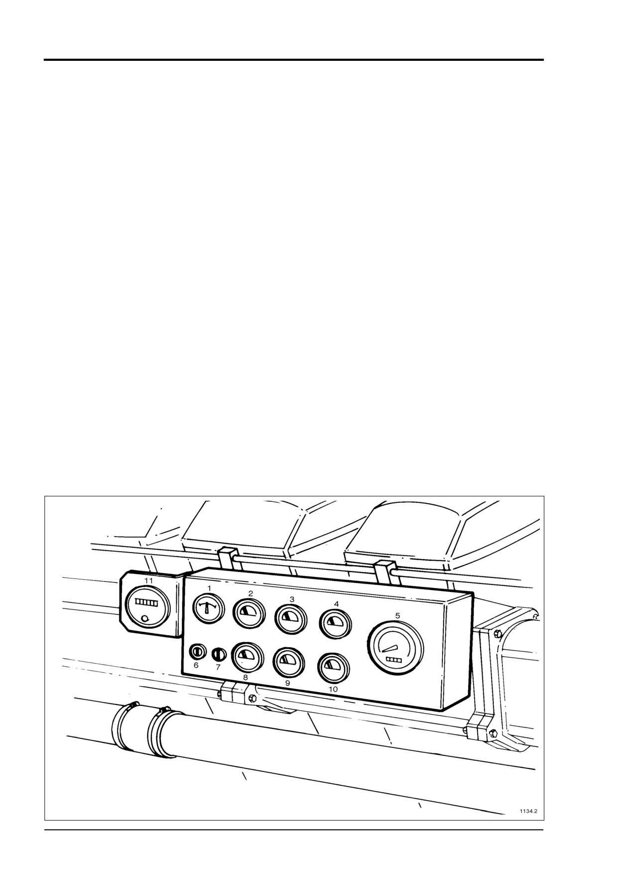
DESCRIPTION
The instrument panel is flexibly mounted on
the side of the engine between the air
manifold flanges. Some instruments are
duplicated giving readings for A and B bank
(see Fig. 5).
(1) Battery charging rate
(2) Coolant temperature 'A' bank
(3) Lubricating oil temperature 'A' bank
(4) Lubricating oil pressure 'A' bank
(5) Taco and hours run
(6) Keyswitch
(7) Fuse holder
(8) Coolant temperature 'B' bank
(9) Lubricating oil temperature 'B' bank
(10) Lubricating oil pressure 'B' bank
(11) Exhaust temperature gauge (when
fitted)
Fig. 5
22
4012/16 Gas, February 1998
INSTRUMENT PANEL
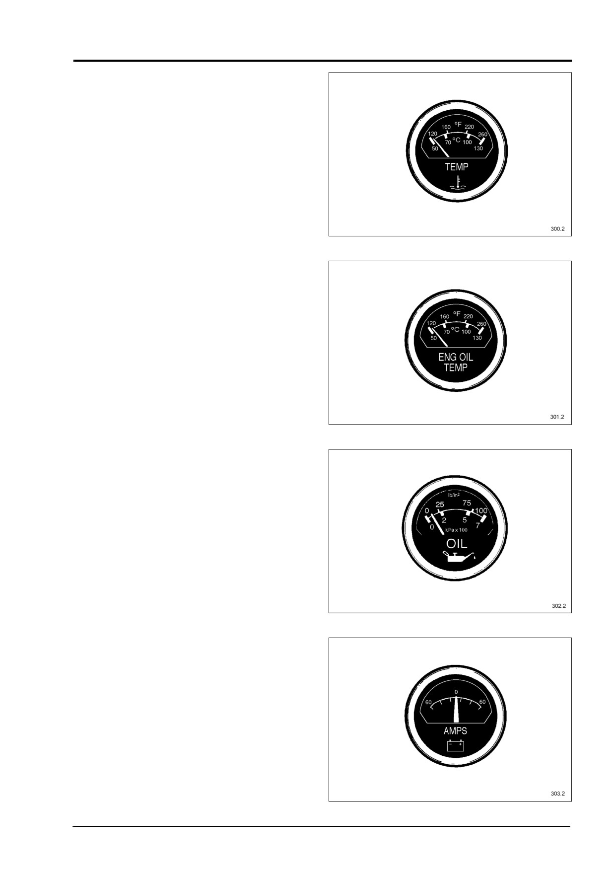
Engine water temperature gauge
(Fahrenheit/Centigrade) Fig. 6
The coolant temperature during normal
operation should be between 65°C - 85°C
(149°F - 185°F). If the temperature should
rise above 93°C (200°F) for a prolonged
period of time, stop the engine and investi-
gate the cause. The engine should, on the
other hand, not be run at too low a tempera-
ture for long periods either.
Fig.
6
Engine oil temperature gauge (Fahrenheit/
Centigrade) Fig. 7
The lubricating oil temperature should be
between 80°C - 90°C (176°F - 194°F) when
the engine is hot. If the temperature should
rise above 115°C (240°F), stop the engine
immediately and investigate the cause.
Engine oil pressure gauge Fig. 8
(pounds per square inch/kiloPascal x 100)
The lubricating oil pressure should be
between 300 - 350 kPa (45 - 50 lb/in2) when
the engine is hot. If the pressure should
Fig.
7
drop below 200 kPa (30 lb/in2) at higher
engine speeds than idling, stop the engine
immediately and investigate the cause.
Ammeter (Ampere) Fig. 9
The ammeter indicates at what charging
current the battery is being charged by the
alternator, or to what extent current is taken
from the battery without the battery being
recharged.
Fig. 8
Fig. 9
4012/16 Gas, February 1998
23
INSTRUMENT PANEL
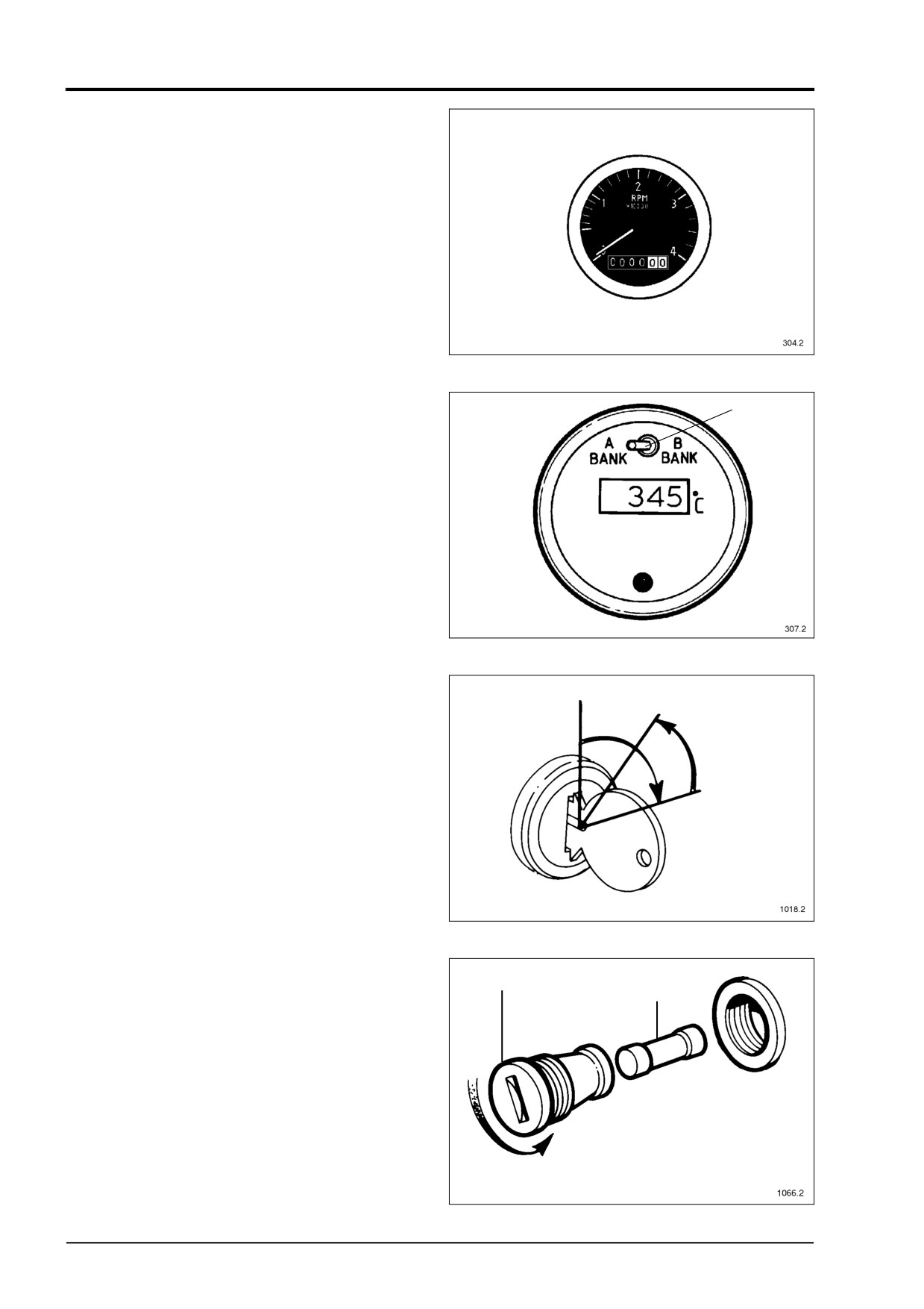
Engine tachometer and hour counter
(revolutions per minute x 1000 and hours)
(see Fig. 10).
The electrically operated tachometer/hour
counter shows the speed of the engine in
rev per min. and the actual operating hours
the engine has run. The tachometer/hour
counter starts operating from an alternator
voltage of 12 V onwards, which has already
been reached at engine idling speed.
Fig.
10
Exhaust temperature gauge (optional)
Temperature range -20 +800°C
The gauge shows readings of turbine outlet
1
temperature and is switched from A to B
bank using the button (1) (see Fig. 11).
NOTE: Early engines may require a dry cell
9 volt battery.
Key switch (3 position) (Off/run/start)
The hand operated keyswitch with switch
lock is moved by a separate key to the posi-
tions shown, (see Fig. 12) viewed from front
of switch.
Fig.
11
Fuse holder
To protect the instrument panel a 2 amp fuse
1
is fitted to remove the fuse (1) unscrew its
2
holder (2) (see Fig. 13).
3
Fig. 12
2
1
Fig. 13
24
4012/16 Gas, February 1998
OPERATING INSTRUCTIONS
3.
Starting (manual)
FINAL CHECKS AND INITIAL STARTUP
Gas supply train must comply with British
3.1)
Turn on gas at manual valve.
gas Code IM17. See Fig. 1 page 16 in the
3.2)
Press start button/turn ignition
Workshop Manual. Also gas pipework up to
key.
the solenoid operated valves must be tested
3.3)
Governor now energised.
at twice working pressure to ensure gas
3.4)
Starter engages, starts to crank.
tightness and any leaks rectified.
Automatic 3 second purge time
determined by control panel.
3.5)
Ignition on, gas solenoid valves
IMPROPER
WARNING
open.
OPERATION OF A
3.6)
Engine starts, starter disengages,
GAS ENGINE CAN BE DANGERHOUS.
runs up to rated speed.
BE PREPARED TO CHECK FOR GAS
3.6.1)
If engine fails to start, investigate
LEAKS AFTER THE SOLENOID VALVES
the following probable causes:
AS SOON AS THE ENGINE STARTS,
a)
High or low gas pressure.
USING A LEAK DETECTING FLUID.
b)
Ignition system grounded.
STOP THE ENGINE AND RECTIFY ANY
c)
Governor failed to energise.
LEAK FOUND.
d)
Low cranking speed.
3.6.2)
Try again once more only
1. Starting and stopping must be on no
commencing with 3.2 above.
load.
3.7)
When engine is running, check oil
pressure, warm engine through
2. For automatic start and stop sequence
and apply the load.
see Fig. 14 on page 27.
3.8)
Check engine condition
at full
load, oil pressure,
jacket
coolant
IF THE ENGINE
WARNING
and charge
air
coolant
FAILS TO START
temperatures.
AFTER TWO ATTEMPTS, TURN OFF
THE GAS SUPPLY AND INVESTIGATE
THE CAUSE. BEFORE ATTEMPTING
TO RESTART THE ENGINE IT MUST
BE PURGED OF GAS. TO DO THIS,
WITH THE GAS SUPPLY AND THE
IGNITION SYSTEM TURNED OFF,
CRANK THE ENGINE WITH THE
STARTER FOR NO MORE THAN 30
SECONDS. THIS SHOULD REMOVE
ANY BUILD-UP OF GAS FROM THE
ENGINE AND EXHAUST SYSTEM.
ALTERNATIVELY THE SYSTEM MAY
BE PURGED WITH COMPRESSED
AIR. ALWAYS BE IN A POSITION TO
STOP THE ENGINE IN THE EVENT OF
A MALFUNCTION BY TURNING OFF
THE GAS SUPPLY OR IN AN
EMERGENCY BY PRESSING THE
RED BUTTON, WHICH REMAINS OFF
UNTIL RESET.
4012/16 Gas, February 1998
25
OPERATING INSTRUCTIONS
4. Stopping
4.1)
Remove load, run for
3 to
5
minutes to reduce combustion
system
temperatures
and
localised boiling of coolant and
to prevent oil carburizing in the
turbocharger bearing housing.
4.2)
Stop engine by de-energising
gas solenoid valves and
governor. DO NOT press the
red stop button for normal
stopping procedure.
If
the
ignition is switched off
the
system will be left full of gas, and
must be purged.
DO NOT RUN THE
WARNING
ENGINE
EXCESSIVELY AT RATED SPEED ON
NO LOAD. IF THE ENGINE IS NOT
BEING USED, SHUT IT DOWN.
Excessive running of the engine at rated
speed no load results in a high depression in
the cylinders, leading to high oil consumption
and a build up of deposits on spark plugs,
valves and pistons.
26
4012/16 Gas, February 1998
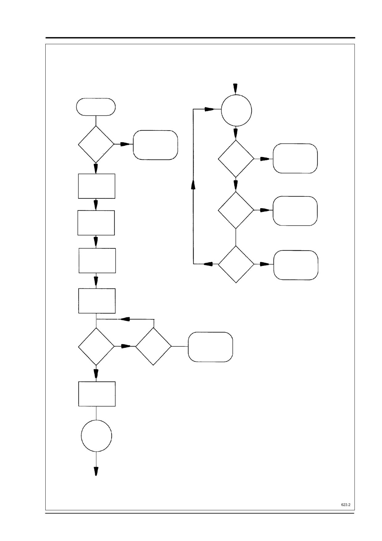
OPERATING INSTRUCTIONS
GAS ENGINE START/STOP SEQUENCE (AUTOMATIC)
START SIGNAL
RECEIVED
ENGINE
RUNNING
IS GAS
NO
PRESSURE
LOW GAS PRESSIRE
WITHIN
ALARM & LOCKOUT
LIMITS?
SWITCH OFF
YES
OVER SPEED
IGNITION SYSTEM
FAULT?
& DE-ENGERGISE
GAS VALVES
YES
ENERGISE
NO
GOVERNOR
OTHER
YES
DE-ENERGISE
ENGINE
GAS VALVES
FAULT?
ENERGISE STARTER
MOTOR & CRANK
TIMER
CRANK FOR
NO
YES
3 SECONDS
STOP
DE-ENERGISE
(PURGE SYSTEM)
ENGINE?
GAS VALVES
ENERGISE GAS
VALVES & IGNITION
CONTINUE
CRANKING
NO
NO
YES
FAIL TO START
HAS ENGINE
MAX CRANKING
TIME REACHED?
LOCKOUT
STARTED?
YES
DE-ENERGISE
STARTER MOTOR
ENGINE
RUNNING
Fig. 14
4012/16 Gas, February 1998
27
MAINTENANCE PROCEDURES
Towards the rear of this section there is a
A
check list sheet for continuous duty
generator sets which is to be used as a
guide for operators and maintenance
personnel.
B
The following schedule details some of the
maintenance to be carried out as in the
maintenance check lists, however not all are
detailed. In these cases please refer to the
Workshop Manual.
The schedule within this section will be
Fig. 15
perfectly suitable for an engine working
under average conditions. If your engine is
COOLANT LEVEL
working under particularly dirty or dusty
conditions, more frequent servicing will be
THE COOLING
WARNING
necessary particularly in respect of the
SYSTEM IS
lubricating oil and air cleaners. Correct and
PRESSURISED - DO NOT REMOVE THE
regular maintenance will help prolong
FILLER CAP WHEN THE ENGINE IS
engine life.
HOT. HAND PROTECTION MUST BE
WORN.
MAKE QUITE
WARNING
CERTAIN THE
ENGINE CANNOT BE STARTED
With the engine stopped remove the
BEFORE UNDERTAKING ANY
radiator cap; the coolant should be 25 mm
MAINTENANCE, PARTICULARLY IN THE
(1") below the top of the filler neck. If the
CASE OF AUTOMATICALLY STARTING
level is low top up with a solution of water
GENERATING SETS OR REMOTE
and inhibitor or water and anti-freeze similar
to that already in the engine. Refer to
STARTING ENGINES.
Engine Data section pages 7 to 10.
DAILY INSPECTION
LEAKS
LUBRICATING OIL LEVEL
Visually check the engine for gas, oil,
With the engine stopped for at least 5 min-
coolant and exhaust leaks, repairing where
utes:-
necessary.
i)
Withdraw the dipstick and wipe clean.
ii)
Re-insert the dipstick fully into the
WEEKLY
sump.
Deal with items under DAILY INSPECTION.
iii) Wait for at least
5 seconds, withdraw
and check the oil level in relation to the
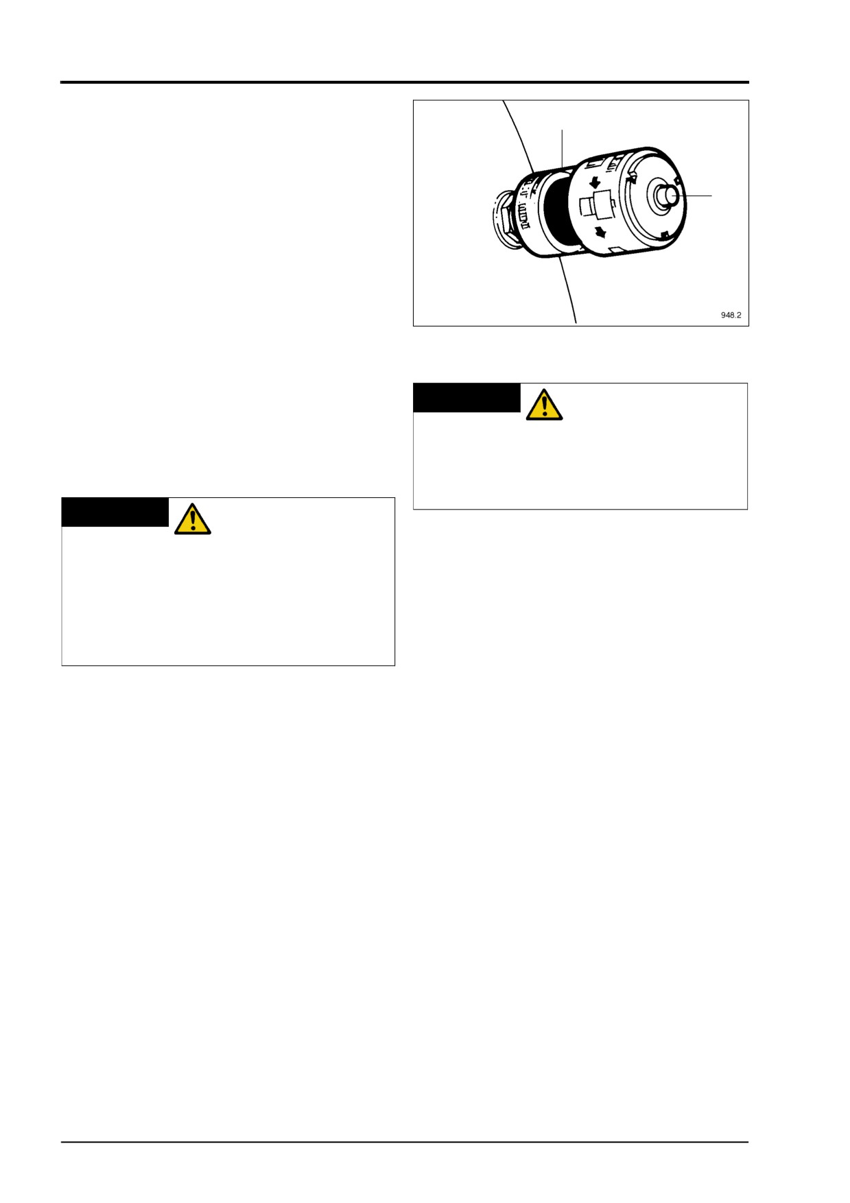
AIR CLEANER RESTRICTION INDICATOR
two marks on the dipstick.
The middle section of the restriction indicator
iv) Repeat operation
(i)
(ii)
(iii) at least
'A' will remain clear while the air cleaner is in
twice, until identical readings are
a serviceable condition. When the filter
observed.
reaches its contamination limit the restriction
If the oil level is below the top mark add
indicator will sense the change in manifold
sufficient of the same grade as that already
pressure and middle section 'A' will change
in the engine to bring the oil level up to the
to red. At this point the air filter must be
top mark.
changed (see Operators Handbook page
Always replace the filler plug immediately
37). When the air filters have been changed
replenishment is completed.
reset the indicator by pressing button 'B'.
(See Fig. 15).
28
4012/16 Gas, February 1998
MAINTENANCE PROCEDURES
BATTERIES
HAND PROTECTION
WARNING
MUST BE WORN
WHEN CHECKING ELECTROLYTE
LEVEL IN THE BATTERY. INFLAMMABLE
GAS IS GIVEN OFF BY THE BATTERY.
DO NOT CHECK WITH A NAKED FLAME.
Remove the plugs or 'quick fill' covers and
check the level of electrolyte. It should be
Fig. 16
13.3
approximately 3 mm above the top of the
plates. If it is low, top-up with pure distilled
NEW OR REBUILT ENGINES
water. Replace the plugs and wipe the top
It is essential to carry out the following
of the battery clean and dry (see page 21
maintenance procedure after the initial 100
for fuller information).
hours.
NOTE: Check the specific gravity
(see
Maintenance Schedule).
FLANGES AND FASTENENERS
Check the torque on all external fasteners
RADIATOR
including the exhaust manifold and
If the engine is working in dirty or dusty
turbocharger flanges. Tighten all hose clips
conditions check that the air passages in the
and pipe unions.
radiator are not becoming choked. They can
be cleaned out by blowing compressed air in
EQUALISE BRIDGE PIECES AND CHECK
the direction opposite to that of the normal
VALVE CLEARANCES
air flow.
(see page
39).
DRAINING WATER FROM THE SUMP
(FOR ENGINE OPERATING ON
LANDFILL GAS)
Unscrew the drain plug in the sump and
drain off the accumulated water content until
oil flows. Tighten the plug, check the oil
level and add the required oil.
FENNER TAPE LOCK BUSHES
MAINTENANCE INSTRUCTIONS
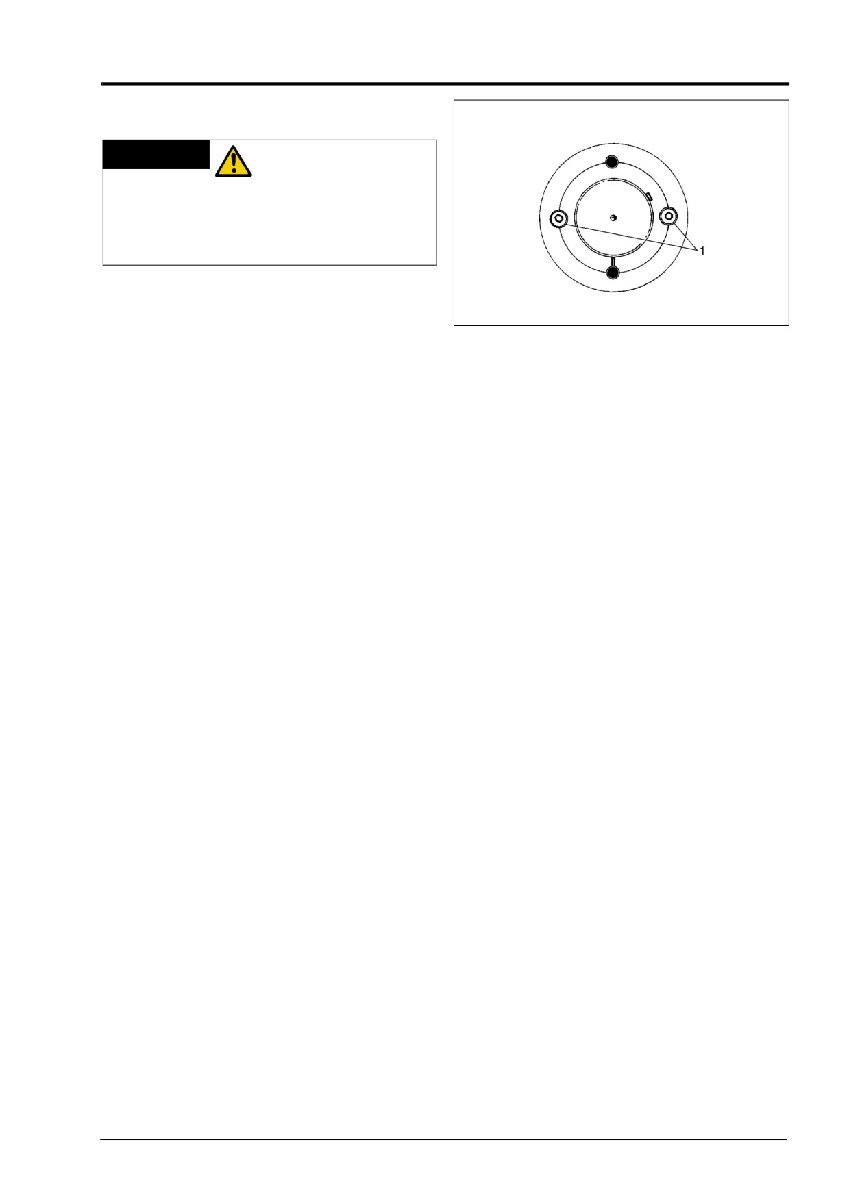
Experience has shown that taper lock
bushes as fitted in the fan pulleys and battery
alternator driven pulley can work loose
shortly after being put into service. Check
using a hexagon wrench to tighten allen
screws (1) Fig. 16 gradually and alternately
until all are tightened to the required torque
(see Torque Settings on pages 11 - 13).
Full details of taper lock pulley see Section
B2 & Section U1 of the Workshop Manual.
Replace any guards removed before running
the engine (see Fig. 16).
4012/16 Gas, February 1998
29
MAINTENANCE PROCEDURES
TURBOCHARGERS
If the engine has been overhauled and a
filter joint fitted to the turbocharger oil feed,
this should now be removed and replaced
with the standard joint. See Service
Bulletin 301 (Revised) and 1.
FOR ENGINES OPERATING ON BIOGAS,
LANDFILL GAS, ETC.
SPARK PLUGS
Clean and reset gaps as described in
Fig.
17
Section N9 of the Workshop manual.
ENGINE OIL AND SPIN-ON FILTERS,
ALSO CENTRIFUGAL OIL FILTER
(WHERE FITTED)
Change engine oil and disposable filters
(see page 34) clean centrifugal filter (see
page 33).
ENGINE ALTERNATOR DRIVE BELT
DISCONNECTING
WARNING
BATTERIES OR ANY
OTHER MEANS OF STARTING.
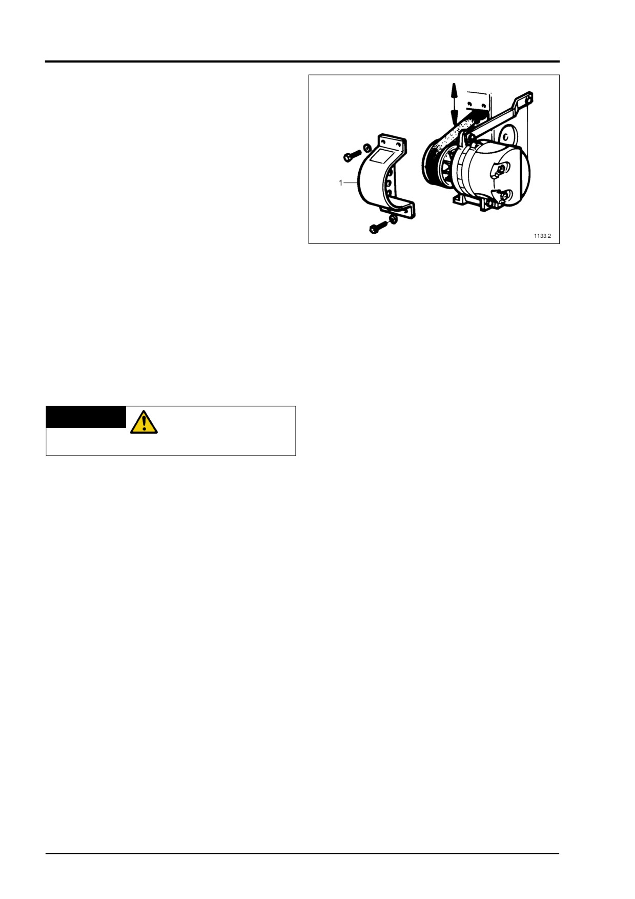
Remove the small mesh guard (1) around
the alternator. The toothed belt used to drive
the alternator relies on tooth engagement to
transmit to load. It does not require
preloading, however a slight initial tension to
ensure that the belt fits snugly round the
pulleys is desirable. Using light pressure
midway between the two pulleys a total
deflection of 1.5 mm (1/16”) is satisfactory
(see Fig. 17). Refit the guard.
SPARK PLUGS
Reset the plug gap as described in Section
N9 and N12 of the Workshop Manual.
ENGINE OIL AND FILTERS
On completion of the first
500 hours
running, change the engine oil and
filters.
30
4012/16 Gas, February 1998
MAINTENANCE PROCEDURES
FAN BEARINGS AND BELTS
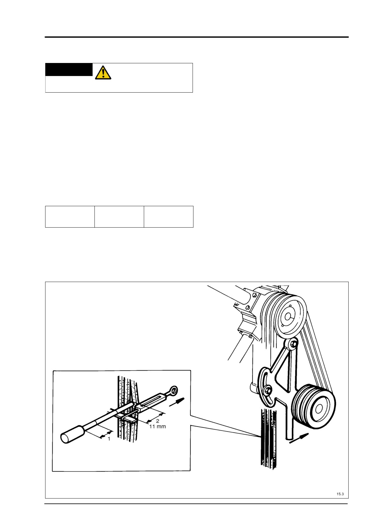
To adjust slacken the jockey pulley pivot and
adjuster bolts, and operate the jockey pulley
lever.
DISCONNECT
WARNING
Moving the jockey pulley lever outwards will
BATTERIES OR ANY
tension the belts and inwards will slacken
OTHER MEANS OF STARTING.
the belts.
The correct tension is obtained by measur-
Remove the mesh guard around the fan
ing the deflection at the mid point between
belts, grease the fan and jockey pulley
the fan pulley and the crankshaft pulley
bearings Fig. 18 using high melting point
when the above force is applied.
lithium based grease
(e.g. Shell Alvania
To apply the force place a rule across the
R.A.)
outside width of the belts and attach spring
Check the tension and condition of the fan
balance as shown Fig. 18 pull on the spring
belts. Using a spring balance and rule, or a
balance until the required force is reached
belt tension indicator, check that the force
and measure the belt deflection.
compares with the kgf (lbf) values shown
Adjust the position of the jockey pulley lever
below for the correct belt deflection. See
until the force on the spring balance and the
Fig. 18.
belt deflection agree with the figures given.
Deflection
kg Force
lb Force
Key
11 mm
3 - 4.3
6,67 - 9.47
(Fig. 18)
1. Force
Fan belts if worn, should be replaced as a
2. Deflection
complete, matching set. Individual belts
should NOT be replaced.
Fig. 18
4012/16 Gas, February 1998
31
MAINTENANCE PROCEDURES
DISCONNECT
WARNING
BATTERIES OR ANY
OTHER MEANS OF STARTING. WHEN
USING COMPRESSED AIR OR
CLEANING AGENTS ALWAYS WEAR
EYE PROTECTION, AND PROTECTIVE
GLOVES.
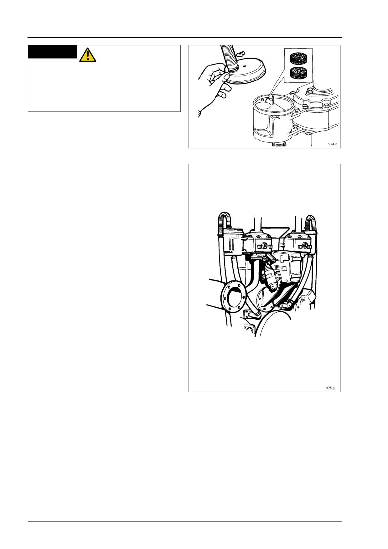
CRANKCASE BREATHER (IMPROVED
DESIGN) FITTED TO LATER ENGINES
Fig.
19
The crankcase breather is mounted on the
side of the thermostat housing Fig. 19 and
is connected to the engine via a flexible pipe
and elbow fitted on the front of the gearcase
(see Fig. 20).
To clean the breather remove the top cover
and withdraw the two wire mesh elements
and wash thoroughly using a suitable
cleaning agent. Shake as dry as possible,
finally blow dry with an compressed air.
Refit the elements into the breather body,
and fit the top cover firmly.
NOTE: When replacing the cover check the
sealing gasket is in good condition and the
cover has located on its dowel
Fig. 20
32
4012/16 Gas, February 1998
MAINTENANCE PROCEDURES
DISCONNECT
WARNING
BATTERIES OR ANY
OTHER MEANS OF STARTING. ALWAYS
WEAR PROTECTIVE GLOVES.
FOR EXTENDED OIL CHANGE PERIOD
(WITH OIL ANALYSIS PROGRAMME) SEE
PAGES 14 - 16 ON ENGINES OPERATING
ON BIO GAS AND OTHER GASES (NOT
BRITISH NATURAL GAS)
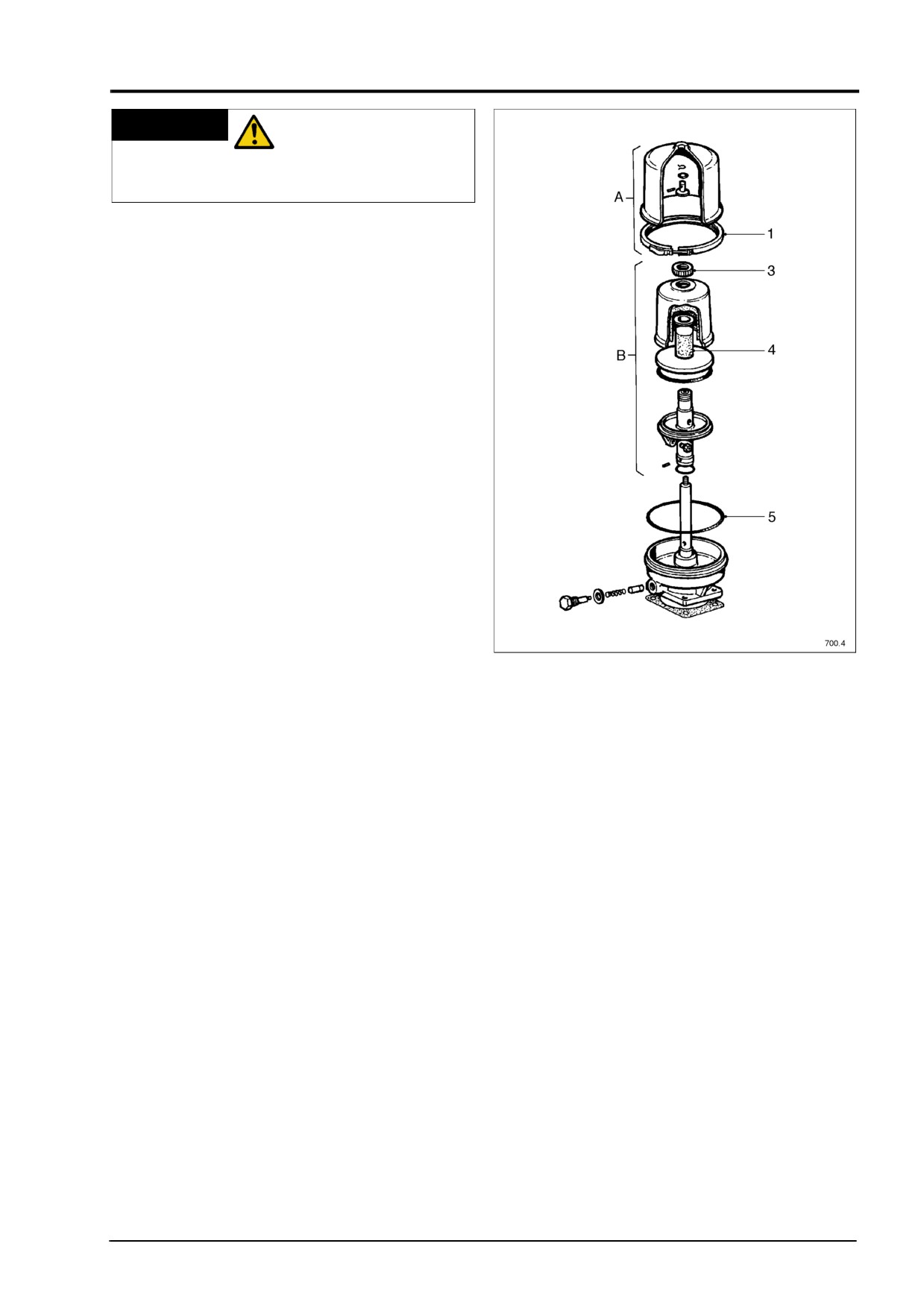
CLEANING THE CENTRIFUGAL
LUBRICATING OIL FILTER
Stop the engine, and allow time for
lubricating oil to drain back to sump.
1.
Slacken safety clamp (1) unscrew cover
nut and lift off cover (A).
(See Fig. 21).
2.
Lift off rotor assembly
(B) having
allowed oil to drain from nozzles. The
rotor should be removed and replaced
on the spindle with extreme care in
order to ensure that bearings are not
damaged.
3.
Secure rotor in dismantling tool T6253/
292. Unscrew rotor cover nut (3) and
Fig.
21
separate rotor cover from body.
4.
Remove standtube (4) using extraction
tool T6253/293 and clean.
9.
Reassemble
filter
complete
checking
5.
Remove sludge from inside the rotor by
that rotor revolves
freely then replace
means of a spatula and wipe clean.
filter body cover. Tighten cover nut and
Ensure that all rotor components are
secure safety clamp. The clamp ring
thoroughly cleaned and free from
should be securely fitted at all times and
deposits of dirt before reassembling the
the filter should not be run without the
rotor. Failure to do so could cause an
clamp ring fitted.
out-of-balance condition which will
10.
With engine running check all joints for
accelerate bearing spindle wear.
leakage. Check for excessive vibration.
6.
Clean nozzle with brass wire. Examine
'O' ring (5) and renew if damaged.
7.
Reassemble rotor complete and tighten
top nut. IMPORTANT: Ensure that the
rotor cover and rotor body are always
matched by balance reference number
and pin location.
DO NOT INTERCHANGE ROTOR
COVERS.
8.
Examine spindle journals, if damaged
or worn replace with body assembly
complete.
4012/16 Gas, February 1998
33
MAINTENANCE PROCEDURES
NOTE: It is suggested that oil analysis tests
are carried out at regular intervals to check
that these maintenance intervals are
satisfactory.
CHANGING ENGINE OIL AND
STANDARD SPIN-ON TYPE
LUBRICATING OIL FILTERS
DISCONNECT
WARNING
BATTERIES OR ANY
OTHER MEANS OF STARTING. ALWAYS
WEAR PROTECTIVE GLOVES.
With the engine stopped, place a suitable
container of at least 150 to 250 litres (33 to
55 gal) beneath the drain plug. Remove the
drain plug and allow the oil to drain. This
operation is best carried out while the
engine is still warm as the thinner oil will
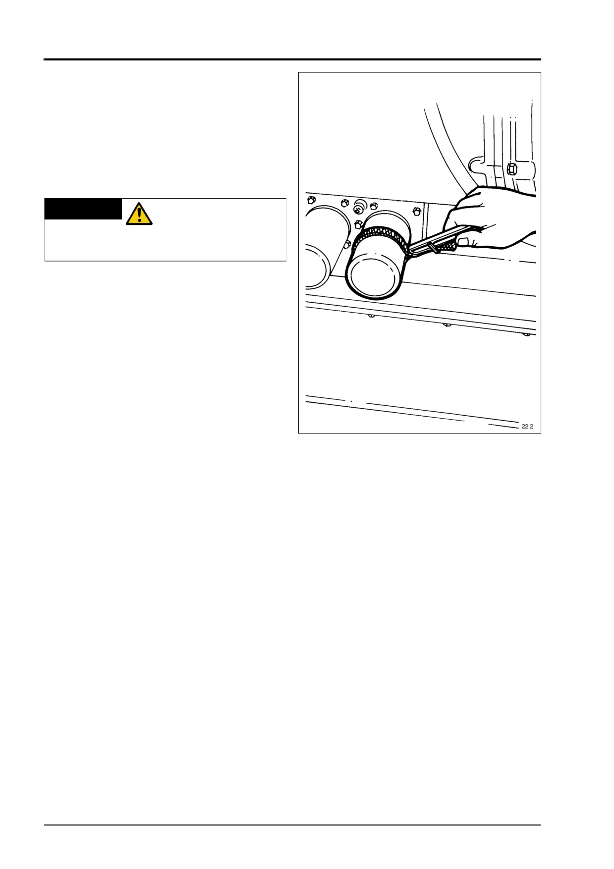
drain more efficiently. While the oil is
draining remove the three oil filters per
bank, turning them anti-clockwise using a
strap wrench see Fig. 22.
Fig.
22
NOTE: Removal of the oil filters will allow an
escape of oil from the filter manifolds, it is
See page 20
for instructions on priming with
therefore recommended that a suitable
the semi-rotary pump.
container of at least 5 litres (1 gal) capacity
Stop cranking the engine and visually check
is positioned under each filter prior to
the engine for oil leaks, top up the oil level.
removal.
Wipe clean the sealing faces and threaded
bosses of the oil header. Smear engine oil
on the captive rubber sealing ring and
carefully screw each new filter up to the oil
header using firm hand pressure only.
Use only genuine Perkins oil filters. The use
of other filters may cause serious damage to
the engine.
Refit the drain plug and fill the engine with
the appropriate grade of new oil (see pages
11-13). Ensure that the gas supply is turned
off, also the switch on the control panel is in
the stop position, and the ignition is
grounded to prevent the engine firing. Turn
the keyswitch to the start position, and crank
the engine over until the oil pressure gauge
registers 0.4 kg/cm² (5 lb/in²).
Continue cranking for a further 10 seconds
which will ensure the oil has reached the
turbocharger bearings.
34
4012/16 Gas, February 1998
MAINTENANCE PROCEDURES
NOTE: If the flexible connections to the filter
DISCONNECT
WARNING
are removed for any reason, it is essential
BATTERIES OR ANY
that they are reconnected correctly to avoid
OTHER MEANS OF STARTING. ALWAYS
unfiltered oil getting into the engine. See
WEAR PROTECTIVE GLOVES.
Fig. 24 on page 36. Failure to change fil-
ters when due can also lead to trouble from
CHANGING THE OPTIONAL CHANGE-
unfiltered oil.
OVER LUBRICATING OIL FILTERS
These special duplex filters are normally
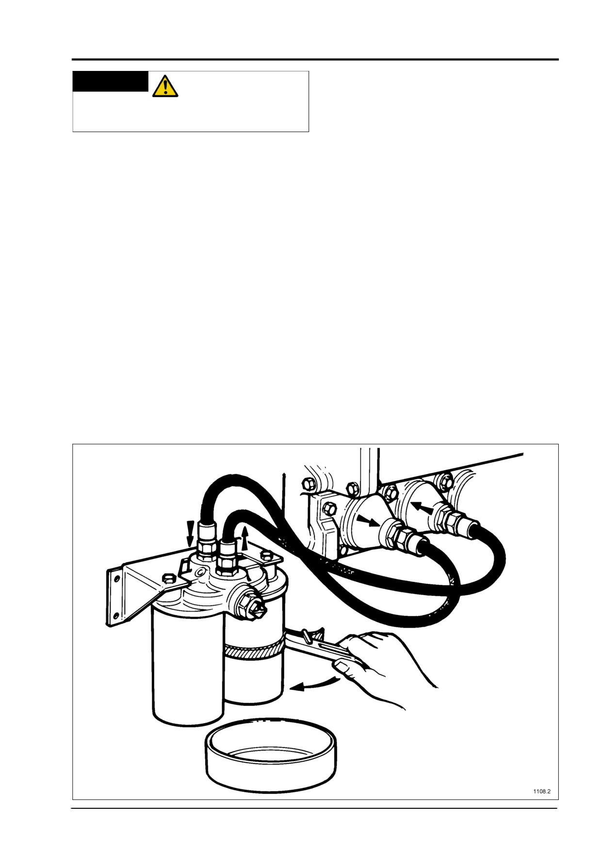
CHANGING THE FILTER ELEMENTS
intended for use on long running engines, or
WHEN THE ENGINE IS STOPPED
where a servicing requirement may occur
All that is necessary is to unscrew the
when it is impractical to stop the engine. For
canisters with a strap wrench as shown in
this reason they are fitted with a three way
Fig.
23, without moving the change-over
change-over valve in the head which enables
valve, as there is no pressure in the system
the elements to be changed, one at a time,
when the engine is stationary. The underside
whilst the engine continues to run. They are
of the header is then wiped clean, and a
normally mounted on the engine, but may be
smear of oil applied to the sealing rings on
remotely mounted, and connected to the
the new canisters, before screwing them up
engine by means of flexible pipes.
by hand and tightening them by no more
than three quarters of a turn after the seals
contact the header. Check the filter for leaks
after the engine is restarted.
Fig. 23
4012/16 Gas, February 1998
35
MAINTENANCE PROCEDURES
NOTE: Prepare for a small spillage of oil
REDUCE ENGINE
WARNING
from the filter as each canister is removed,
SPEED TO IDLING IF
by placing a container of about
5
litres
or
1
CHANGING THE FILTERS WHILST
gallon capacity under the filter.
ENGINE IS RUNNING.
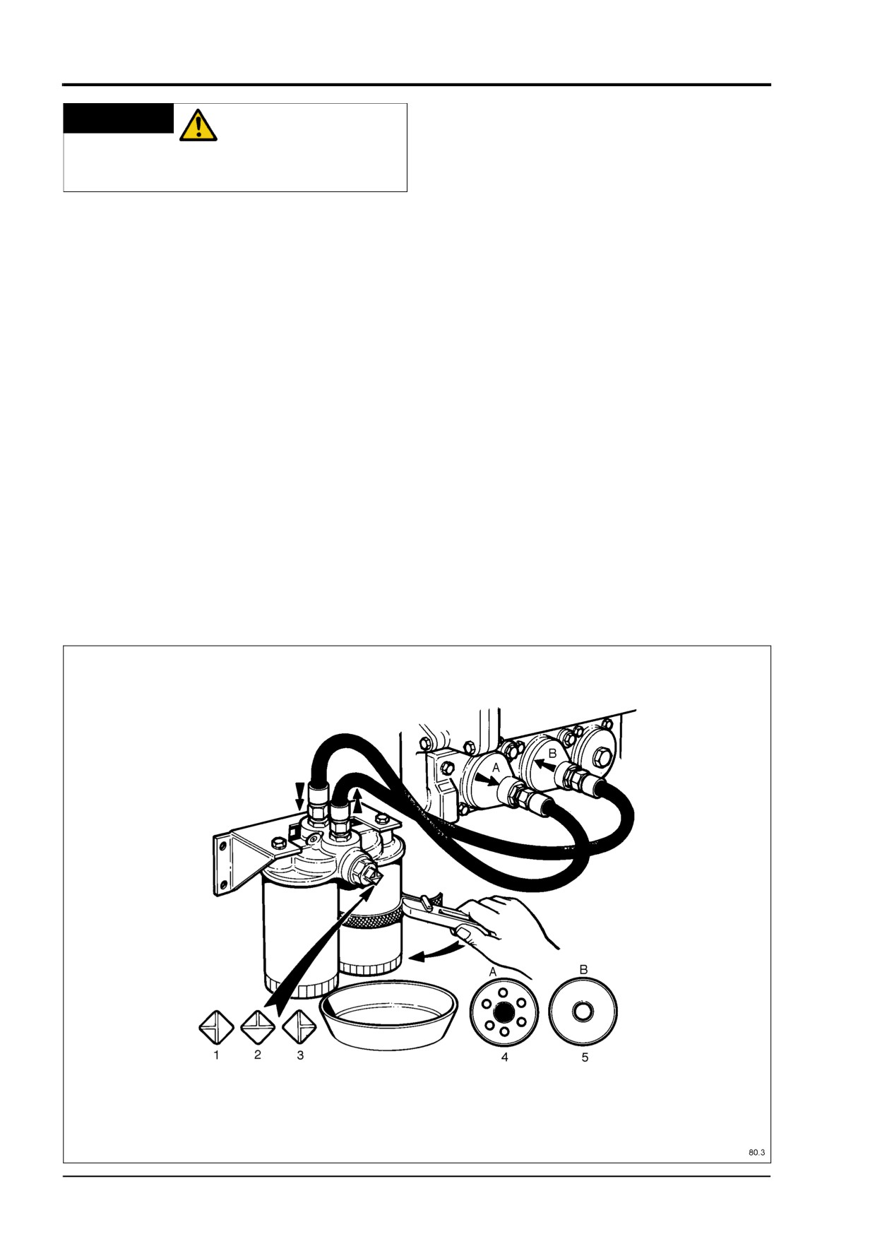
Key
CHANGING THE FILTER ELEMENTS
(Fig. 24)
WITHOUT STOPPING THE ENGINE
1. Change right filter
The normal position of the change-over
2. Normal
valve is with marking on the valve spindle for
3. Change left filter
the spanner showing the leg of the inverted
4. Dirty oil into filter
T pointing upwards when both filter elements
5. Clean oil into engine
are in circuit. Turning the valve with the
spanner provided so that the leg of the T
points to the left, puts the right hand filter out
of service, so that it may be exchanged for a
new one, fill the new filter with clean oil
before fitting. Turning the valve so that the
leg points to the right, puts the left hand filter
out of service, so that this one can now be
exchanged for a new filter canister. The valve
is then returned to its original position, so
that both elements of the filter are back in
service. Check for oil leaks.
Fig. 24
36
4012/16 Gas, February 1998
MAINTENANCE PROCEDURES
DISCONNECT
1
WARNING
BATTERIES OR ANY
OTHER MEANS OF STARTING THE
ENGINE.
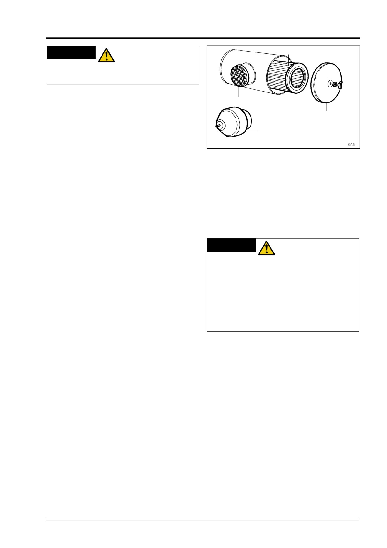
CHANGING AIR FILTER (SEE SECTION
2
A1 IN THE WORKSHOP MANUAL)
3
STANDARD
Remove the end cover (3) of the air filter
4
housing, after unscrewing the retaining wing
Fig. 25
nut, carefully lift out the paper air filter
element (1). For servicing the element see
(b) Dust accumulation on the inlet side of
General Servicing Instructions below.
the housing is usually caused by
When all servicing procedures are
leaking gaskets and/or damaged gasket
completed, fit the new or cleaned element
surfaces. If this condition exists, leaking
into the housing. When fitting the end cover
gaskets should be replaced and
ensure it has seated fully in the housing
damaged gasket surfaces should be
before tightening the wing nut. Inspect and
repaired before placing the unit back
tighten all air filter connection before
into service.
resuming equipment operation (see Fig. 25).
REPLACE ANY
HEAVY DUTY
WARNING
ELEMENT WHICH IS
The heavy duty air filter incorporates a
DAMAGED.
cyclone unit (4) fitted to the air intake of the
NEVER “BLOW” DIRT OUT OF THE
filter
(replacing the mesh guard (2)). To
FILTER HOUSING. THIS MAY
clean the cyclone unit remove it from the air
INTRODUCE DUST INTO THE ENGINE.
filter and blow out any foreign matter within
INSTEAD, USE A CLEAN, DAMP CLOT,
the unit. Changing the paper air filter
DO NOT OIL THE ELEMENT.
element the procedure is the same as for the
WHEN USING COMPRESSED AIR
standard air filter above.
ALWAYS WEAR EYE PROTECTION.
GENERAL SERVICING INSTRUCTIONS
ELEMENT CLEANING
Servicing procedures include cleaning or
If the filter element is in good condition with
replacing the filter element, cleaning the filter
light dust contamination on its outer surface
housing, and assuring that all piping and
and the air flow restriction indicator
(see
hose connection from the filter outlet to the
Page
28) has not been triggered, the
turbocharger intake are sealed airtight.
element can be cleaned using a vacuum
cleaner or compressed air.
FILTER ELEMENT SERVICE
Clean the exterior of the filter housing and
then carefully remove the element. Inspect
the "clean air side" of the element and the
outlet side of the filter housing for any
unusual dust accumulations.
(a) Dust accumulations on the clean air side
of the element usually indicates a rupture
in the filter medium.
Immediate
replacement of the element is
necessary.
4012/16 Gas, February 1998
37
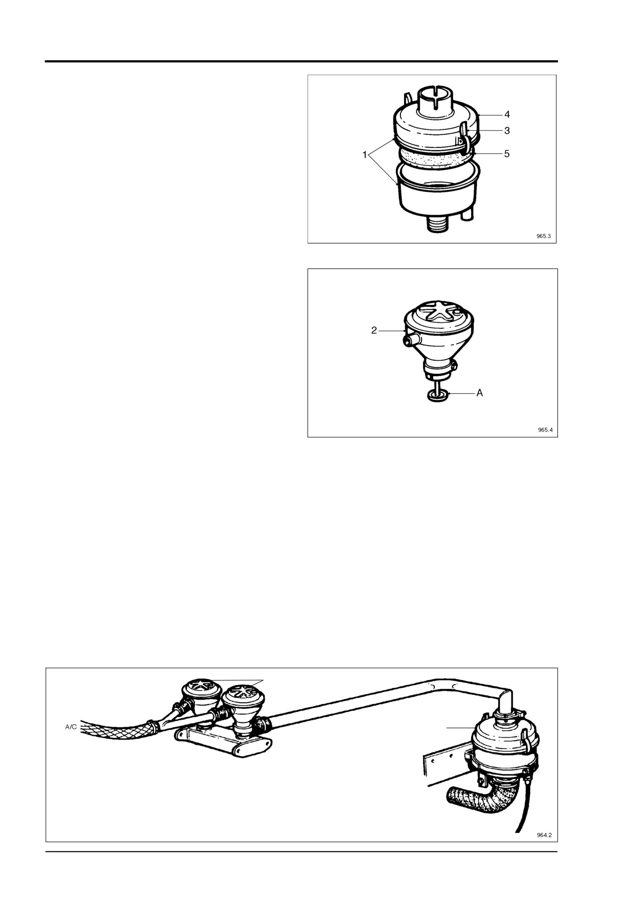
MAINTENANCE PROCEDURES
CLOSED CIRCUIT BREATHER
The closed circuit breather separators (1)
are mounted on each side of the gearcase
and are connected to the carburettor mixer
inlet via the breather valve (2). To clean the
breather separator remove the complete
unit from the engine (see Fig. 26).
Release the retaining clips and remove the
top cover (4) from the filter body. Remove
the foam element (5) check it for oil sludge
saturation wash thoroughly in a suitable
Fig.
26
cleaning agent, shake of excess solvent and
blow dry with compressed air. Clean any oil
sludge deposits from the filter body re-
assemble and fit to engine.
The breather valve (2) is mounted at the
flywheel end of the engine directly under the
air filter. To remove release the pipe clips
(see Fig. 27) and pull away from the valve
manifold. Wash the breather thoroughly in a
suitable solvent paying particular attention
to any deposits on the internal are of the
breather. Shake as dry as possible and
blow dry with compressed air.
Fig.
27
Before refitting ensure that the cup (A) at the
base of the two breather valves are full of
clean engine oil (see Fig. 27).
2
1
Fig. 28
38
4012/16 Gas, February 1998
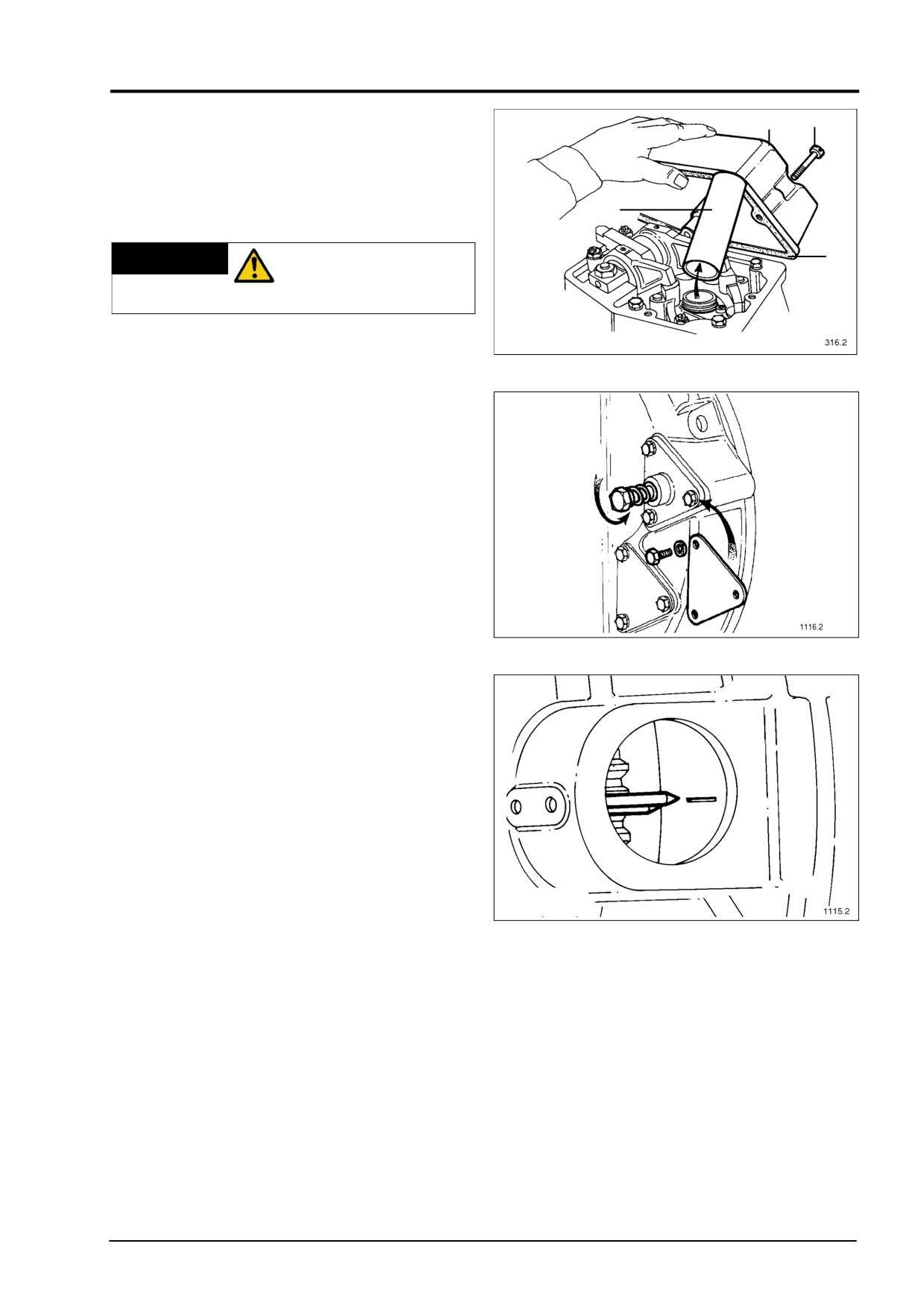
MAINTENANCE PROCEDURES
EQUALISING BRIDGE PIECES AND
2
1
SETTING VALVE CLEARANCES
NOTE: The bridge pieces must be set before
attempting to set the valve clearances.
4
DISCONNECT
3
WARNING
BATTERIES OR ANY
OTHER MEANS OF STARTING.
Fig.
29
Remove the 4 screws (1) from the rocker
cover (2), lift off the cover peel off and throw
away the old gasket (3) Pull the spark plug
lead tube (4) from the spark plug bush (see
Fig. 29).
To equalise the bridge pieces the
appropriate valves must be rocking, use the
table below.
In order that the engine may be rotated
while the batteries are disconnected a
special cranking device
(SE253) can be
fitted to the spare starter motor hole in the
1
2
flywheel housing (see Fig. 30). Using a
Fig.
30
socket and ratchet wrench press against the
spring loaded bolt head until the pinion
engages with the flywheel gear then crank
the engine to the desired position.
If the valves required to be rocking are
closed rotate the engine one revolution
which will bring these valves to the rocking
position. The flywheel housing has an
inspection hole directly below the
turbocharger through which the flywheel
markings may be seen to line up with the
pointer set in the flywheel housing (see Fig.
31).
Fig.
31
The flywheel is marked: T.D.C. (Top Dead
Centre)
4012TESI
4016TESI
A1-A6
A1-A8
A5-A2
A3-A6
A3-A4
A7-A2
B1-B6
A5-A4
B5-B2
B1-B8
B3-B4
B3-B6
B7-B2
B5-B4
4012/16 Gas, February 1998
39
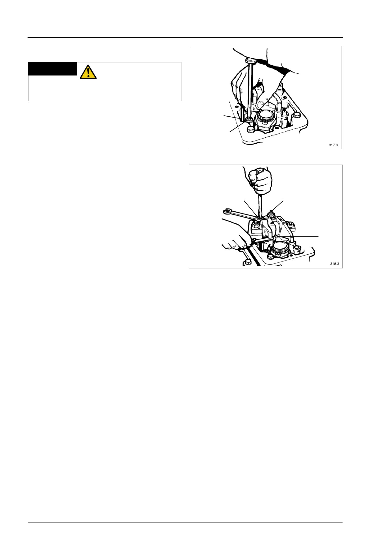
MAINTENANCE PROCEDURES
EQUALISING THE BRIDGE PIECES
DISCONNECT
WARNING
BATTERIES OR ANY
OTHER MEANS OF STARTING THE
ENGINE.
Having rotated the engine to the correct
2
position, check that the inlet and exhaust
rockers have clearance before continuing
1
with the next operation. Loosen the lock nut
Fig.
32
(1) on each bridge piece, screw the adjuster
(2) out until the fixed side of the bridge piece
rests on its valve, hold the top edge down
with one hand then screw the adjuster down
until you feel it touch the valve, thereby
equalising valve lift. Tighten the lock nut
3
2
without moving the adjuster (see Fig. 32).
SETTING VALVE CLEARANCE
With both bridge pieces equalised check the
1
valve clearance of 0.4 mm (0.016") inlet and
exhaust using a feeler gauge (1). If adjustment
is required loosen the lock nut (2) and using
Fig.
33
the adjuster screw (3) set the clearance.
Tighten the lock nut without moving the
adjuster
(see Fig.
33). The feeler gauge
should be a slide fit between the rocker and
bridge piece thereby giving the correct
clearance. Refit the rocker cover with a new
gasket.
ENGINE 4012TESI
SET BRIDGE PIECE
VALVES ROCKING ON
AND VALVE CLEARANCE
CYLINDER NO.
T.D.C.
ON CYLINDER NO.
A1 & A6
A6
A1
B1 & B6
B1
B6
A2 & A5
A2
A5
B2 & B5
B5
B2
A3 & A4
A4
A3
B3 & B4
B3
B4
A1 & A6
A1
A6
B1 & B6
B6
B1
A2 & A5
A5
A2
B2 & B5
B2
B5
A3 & A4
A3
A4
B3 & B4
B4
B3
40
4012/16 Gas, February 1998
MAINTENANCE PROCEDURES
ENGINE
4016TESI
SET BRIDGE PIECE
VALVES ROCKING ON
AND VALVE CLEARANCE
CYLINDER NO.
T.D.C.
ON CYLINDER NO.
A1 & A8
A8
A1
B1 & B8
B8
B1
A3 & A6
A6
A3
B3 & B6
B6
B3
A7 & A2
A2
A7
B7 & B2
B2
B7
A5 & A4
A4
A5
B5 & B4
B4
B5
A1 & A8
A1
A8
B1 & B8
B1
B8
A3 & A6
A3
A6
B3 & B6
B3
B6
A7 & A2
A7
A2
B7 & B2
B7
B2
A5 & A4
A5
A4
B5 & B4
B5
B4
4012/16 Gas, February 1998
41
MAINTENANCE PROCEDURES
BRITISH NATURAL GAS, BIOGAS AND OTHER GASES
CONTINUOUS DUTY CHECK LIST (BASED ON ENGINES RUNNING AT 1500 RPM NORMAL
OPERATION AND STANDARD OIL CHANGE PERIOD)
CONTINUOUS DUTY MAINTENANCE
OPERATIONS TO BE PERFORMED
A B C D E F G
SYSTEM
OPERATION
DESCRIPTION
Lubricating
Check
For leaks and oil pressure
•
•
•
•
•
•
•
•
Engine oil level
•
•
•
•
•
•
•
Change
Full flow filters (normal or change-over)
•
★
•
•
•
•
Engine oil
•
★
•
•
•
•
Clean
Crankcase Breather (and centrifugal oil filter, if fitted)
★
•
•
•
•
Closed circuit crankcase breather
•
•
•
•
Change
Closed circuit crankcase breather separator elements
•
•
•
•
Cooling
Check
For radiator air restriction
•
•
•
•
•
•
Operation of coolant heater
•
•
•
•
Hoses and connections for leaks
•
•
•
•
•
•
•
•
Coolant level and operating temperature
•
•
•
•
•
•
•
Antifreeze & inhibitor concentration
•
•
•
•
Belt condition & tension
•
•
•
•
•
Change
Fan and alternator belts
•
•
•
Grease
Fan hub & jockey pulley bearing
•
•
•
•
•
Change
Coolant
EVERY 12 MONTHS
Clean
Cooling system
Air
Check
For leaks
•
•
•
•
•
•
•
•
Air cleaner restriction
•
•
•
•
•
•
•
Pipes and connection
•
•
•
•
Change
Air cleaner element
•
•
•
•
Gas
Check
For leaks
•
•
•
•
•
•
•
•
Check
Governor linkage
•
•
•
•
Check
Gas lines & connections
•
•
•
•
•
Renew
Diaphragm in regulator
•
Check
Wiring (incl. high tension lead, renew if required)
•
•
Clean
Spark plugs (reset)
■
•
•
•
•
Adjust
Bridge pieces and valves
First 100 hours and then
•
•
•
•
Change
Spark plugs
■
•
•
•
Exhaust
Check
For leaks
•
•
•
•
•
•
•
•
For exhaust restrictions
•
•
•
•
Clean
Turbocharger comp wheel & diffuser
•
•
•
•
Check
Turbocharger bearing clearances
•
•
•
•
Engine
Check
Fenner taper lock bush (First 50 hours)
•
•
•
Related
Check
Vibration damper
•
•
•
Check
Engine mountings
•
•
•
Overhaul
Cylinder heads
•
•
•
Re-ring
Piston (if necessary)
•
•
Overhaul
Engine (new pistons, liners, etc.)
•
Electrical
Check
Battery charging system, ignition system
•
•
•
•
•
•
Battery electroylte level, specific gravity
•
•
•
•
•
•
Belt condition & tension
•
•
•
•
•
Clean & reset magnetic pick-ups
•
•
•
Protection switches & alarms
•
•
•
•
Starter motor mounting bolts & terminals
•
•
•
NOTE: All bolts, hose clips, terminal connections, pipes and joints, should be checked for tightness and leaks after the first 100 hrs and every 3
months
thereafter.
★ First 500 hours then every 1,000 hours for British Natural Gas. For Biogas and other gases, first 250 hrs then every 400 hrs.
■ Clean at first 500 hrs then every 1,000 hrs for British Natural Gas. For Biogas and other gases first 250 hrs then every 400 hrs. Change every 2,000
hrs for British Natural Gas and every 1,000 hrs for Biogas and other gases.
✛ Major inspection at 12,000 hrs for British Natural Gas. For Biogas and other gases at 6,000 hrs check front and rear crankshaft oil seals
▲ Major overhaul at 20,000 hrs for British Natural Gas. For Biogas and other gases at 12,000 hrs
✼ Whichever is sooner.
NOTE: On landfill gas engines drain condensate from sump every week.
42
4012/16 Gas, February 1998
MAINTENANCE PROCEDURES
BRITISH NATURAL GAS
CONTINUOUS DUTY CHECK LIST (BASED ON ENGINES RUNNING AT 1500 RPM NORMAL
OPERATION AND EXTENDED OIL CHANGE PERIOD)
CONTINUOUS DUTY MAINTENANCE
OPERATIONS TO BE PERFORMED
A B C D E F G
SYSTEM
OPERATION
DESCRIPTION
Lubricating
Check
For leaks and oil pressure
•
•
•
•
•
•
•
•
Engine oil level
•
•
•
•
•
•
•
Change
Full flow filters (normal or change-over)
•
★
•
•
•
•
Engine oil
•
★
•
•
•
•
Clean
Crankcase Breather (and centrifugal oil filter, if fitted)
★
•
•
■
•
Closed circuit crankcase breather
•
•
•
•
Change
Closed circuit crankcase breather separator elements
•
•
•
•
Cooling
Check
For radiator air restriction
•
•
•
•
•
•
Operation of coolant heater
•
•
•
•
Hoses and connections for leaks
•
•
•
•
•
•
•
•
Coolant level and operating temperature
•
•
•
•
•
•
•
Antifreeze & inhibitor concentration
•
•
•
•
Belt condition & tension
•
•
•
•
•
Change
Fan and alternator belts
•
•
•
Grease
Fan hub & jockey pulley bearing
•
•
•
•
•
Change
Coolant
Clean
Cooling system
EVERY 12 MONTHS
Air
Check
For leaks
•
•
•
•
•
•
•
•
Air cleaner restriction
•
•
•
•
•
•
•
Pipes and connection
•
•
•
•
Change
Air cleaner element
•
•
•
•
Gas
Check
For leaks
•
•
•
•
•
•
•
•
Check
Governor linkage
•
•
•
•
Check
Gas lines & connections
•
•
•
•
•
Renew
Diaphragm in regulator
•
Check
Wiring (incl. high tension lead, renew if required)
•
•
Clean
Spark plugs (reset)
First 500 hours and then
•
•
•
•
Adjust
Bridge pieces and valves
First 100 hours and then
•
•
•
•
Change
Spark plugs
EVERY 2000 HOURS
Exhaust
Check
For leaks
•
•
•
•
•
•
•
•
For exhaust restrictions
•
•
•
•
Clean
Turbocharger comp wheel & diffuser
•
•
•
•
Check
Turbocharger bearing clearances
•
•
•
•
Engine
Check
Fenner taper lock bush (First 50 hours)
•
•
•
Related
Check
Vibration damper
•
•
•
Check
Engine mountings
•
•
•
Overhaul
Cylinder heads
•
•
•
Re-ring
Piston (if necessary)
•
•
Overhaul
Engine (new pistons, liners, etc.)
•
Electrical
Check
Battery charging system, ignition system
•
•
•
•
•
•
Battery electrolyte level, specific gravity
•
•
•
•
•
•
Belt condition & tension
•
•
•
•
•
Clean & reset magnetic pick-ups
•
•
•
Protection switches & alarms
•
•
•
•
Starter motor mounting bolts & terminals
•
•
•
NOTE: All bolts, hose clips, terminal connections, pipes and joints, should be checked for tightness and leaks after the first 100 hrs and every 3 months
thereafter.
★ Change at first 500 hrs, then every 1000 hrs, until an extended oil change period has been established, which will depend on the
result of a series of analyses (see pages 14-15).
■ Also check front and rear crankshaft oil seals.
✼ Whichever is sooner.
4012/16 Gas, February 1998
43
MAINTENANCE PROCEDURES
BIOGAS AND OTHER GASES (NOT BRITISH NATURAL GAS)
CONTINUOUS DUTY CHECK LIST (BASED ON ENGINES RUNNING AT 1500 RPM NORMAL
OPERATION AND EXTENDED OIL CHANGE PERIOD)
CONTINUOUS DUTY MAINTENANCE
OPERATIONS TO BE PERFORMED
A B C D E F G
SYSTEM
OPERATION
DESCRIPTION
Lubricating
Check
For leaks and oil pressure
•
•
•
•
•
•
•
•
Engine oil level
•
•
•
•
•
•
•
Change
Full flow filter
•
★
•
•
•
•
Engine oil
•
★
•
•
•
•
Clean
Crankcase Breather
•
•
•
•
•
Closed circuit crankcase breather
•
•
•
•
Change
Closed circuit crankcase breather separator elements
•
•
•
•
Clean
Centrifugal lubricating oil filter
First 250 hours and then
EVERY 400 HOURS
Check
Front and rear crankshaft oil seals
•
•
Cooling
Check
For radiator air restriction
•
•
•
•
•
•
Operation of coolant heater
•
•
•
•
Hoses and connections for leaks
•
•
•
•
•
•
•
•
Coolant level and operating temperature
•
•
•
•
•
•
•
Antifreeze & inhibitor concentration
•
•
•
•
Belt condition & tension
•
•
•
•
•
Change
Fan and alternator belts
•
•
•
Grease
Fan hub & jockey pulley bearing
•
•
•
•
•
Change
Coolant
EVERY 12 MONTHS
Clean
Cooling system
Air
Check
For leaks
•
•
•
•
•
•
•
•
Air cleaner restriction
•
•
•
•
•
•
•
Pipes and connection
•
•
•
•
Change
Air cleaner element
•
•
•
•
Gas
Check
For leaks
•
•
•
•
•
•
•
•
Check
Governor linkage
•
•
•
•
Check
Gas lines & connections
•
•
•
•
•
Renew
Diaphragm in regulator
•
Check
Wiring (incl. high tension lead, renew if required)
•
•
Clean
Spark plugs (reset)
First 250 hours and then
★
•
•
•
•
Adjust
Bridge pieces and valves
First 100 hours and then
•
•
•
•
Change
Spark plugs
•
•
•
•
Exhaust
Check
For leaks
•
•
•
•
•
•
•
•
For exhaust restrictions
•
•
•
•
Clean
Turbocharger comp wheel & diffuser
•
•
•
•
Check
Turbocharger bearing clearances
•
•
•
•
Engine
Check
Fenner taper lock bush (First 50 hours)
•
•
•
Related
Check
Vibration damper
•
•
•
Check
Engine mountings
•
•
•
Overhaul
Cylinder heads
•
•
•
Re-ring
Piston (if necessary)
•
•
Overhaul
Engine (new pistons, liners, etc.)
•
Electrical
Check
Battery charging system, ignition system
•
•
•
•
•
•
Battery electrolyte level, specific gravity
•
•
•
•
•
•
Belt condition & tension
•
•
•
•
•
Clean & reset magnetic pick-ups
•
•
•
Protection switches & alarms
•
•
•
•
Starter motor mounting bolts & terminals
•
•
•
NOTE: All bolts, hose clips, terminal connections, pipes and joints, should be checked for tightness and leaks every
3 months.
★ Change first 250 hrs, then every 400 hrs, until an extended oil change period has been established, which will depend on a series of analyses (see
pages 14-15). A centrifugal oil filter (see page 29) must be fitted and cleaned after first 250 hrs then every 400 hrs.
NOTE: It is normal practice when operating on gases other than natural gas for the oil to be continuously analysed at intervals of 100/150 hrs.
✼ Whichever is sooner.
44
4012/16 Gas, February 1998
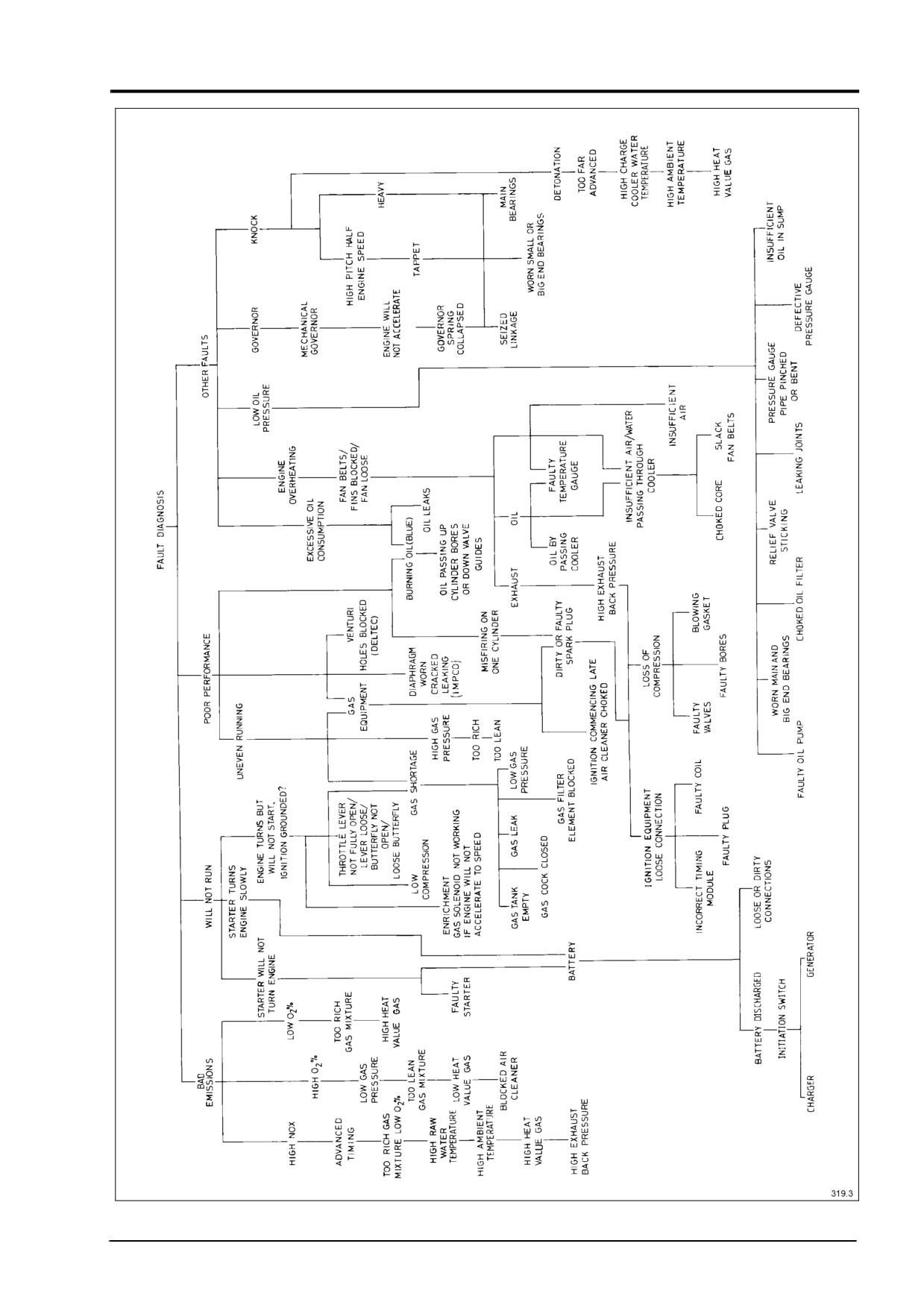
4012 & 4016 GAS ENGINES FAULT TRACING CHART
Fig. 34
4012/16 Gas, February 1998
45
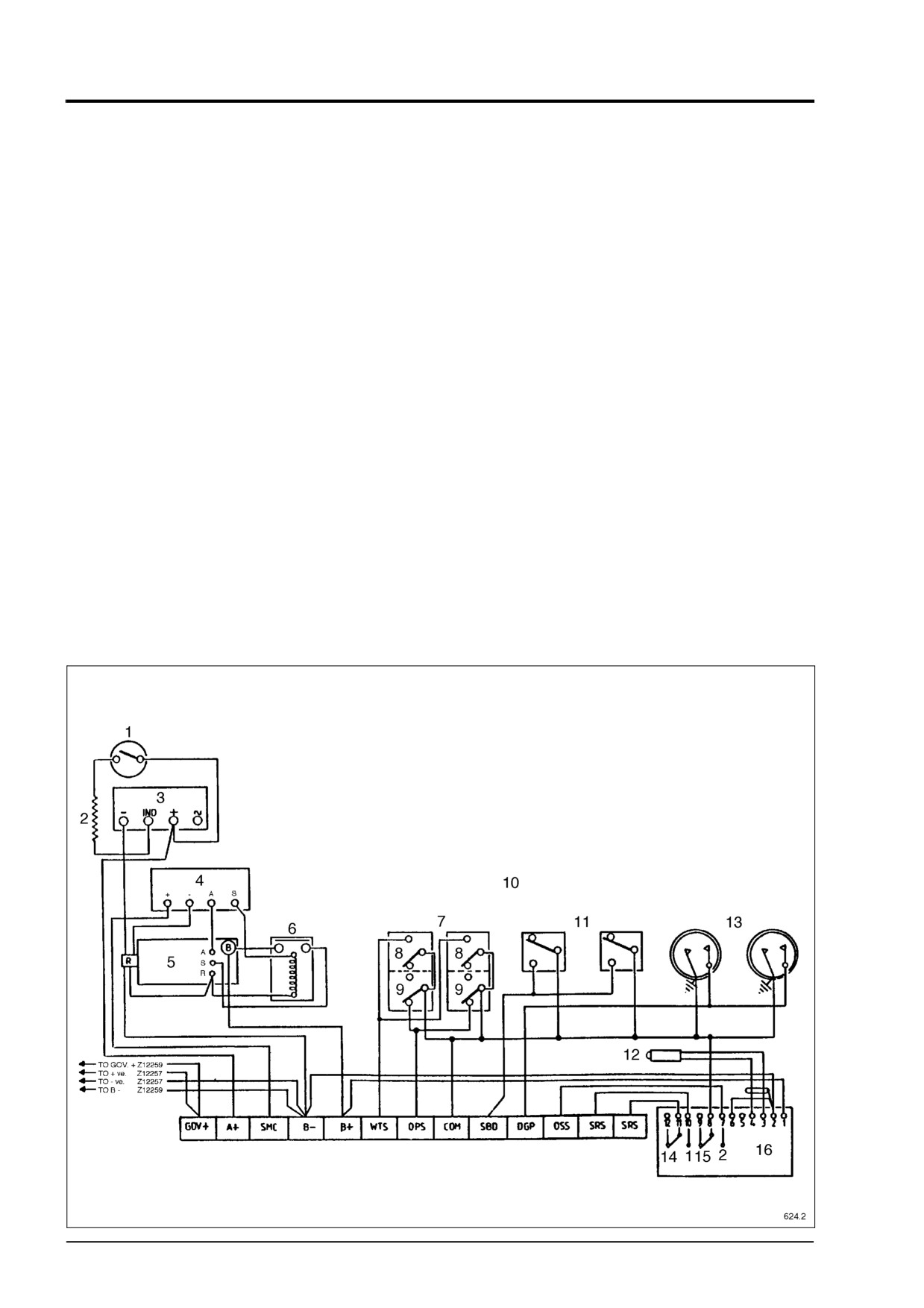
4012/16TESI (MINNOX) WIRING DIAGRAM WITH CAV STARTER AND PROTECTION
SWITCHES
Key
(Fig. 35)
1.
Oil press switch
2.
220Ω5w resistor
3.
Charging alternator
4.
Repeater relay
5.
Start motor
6.
‘Start relay
7.
Engine fault switches left/right banks
8.
Water temp.
9.
Oil press
10. All fault switches close on a fault. One
side of all fault switches are identical. For the
engine to run, immediately on depressing
start button, Gov+ must be fed 24 volt +ve. To
stop the engine break this +ve.
11. Left/right manifold high gas pressure
detector switches
12. Pick-up sensing on flywheel
13. Left/right manifold switch gauges for
manifold out of balance protection
14. Switch speed 700 rpm
15. Switch overspeed
16. Two switch speed unit
Fig. 35
46
4012/16 Gas, February 1998
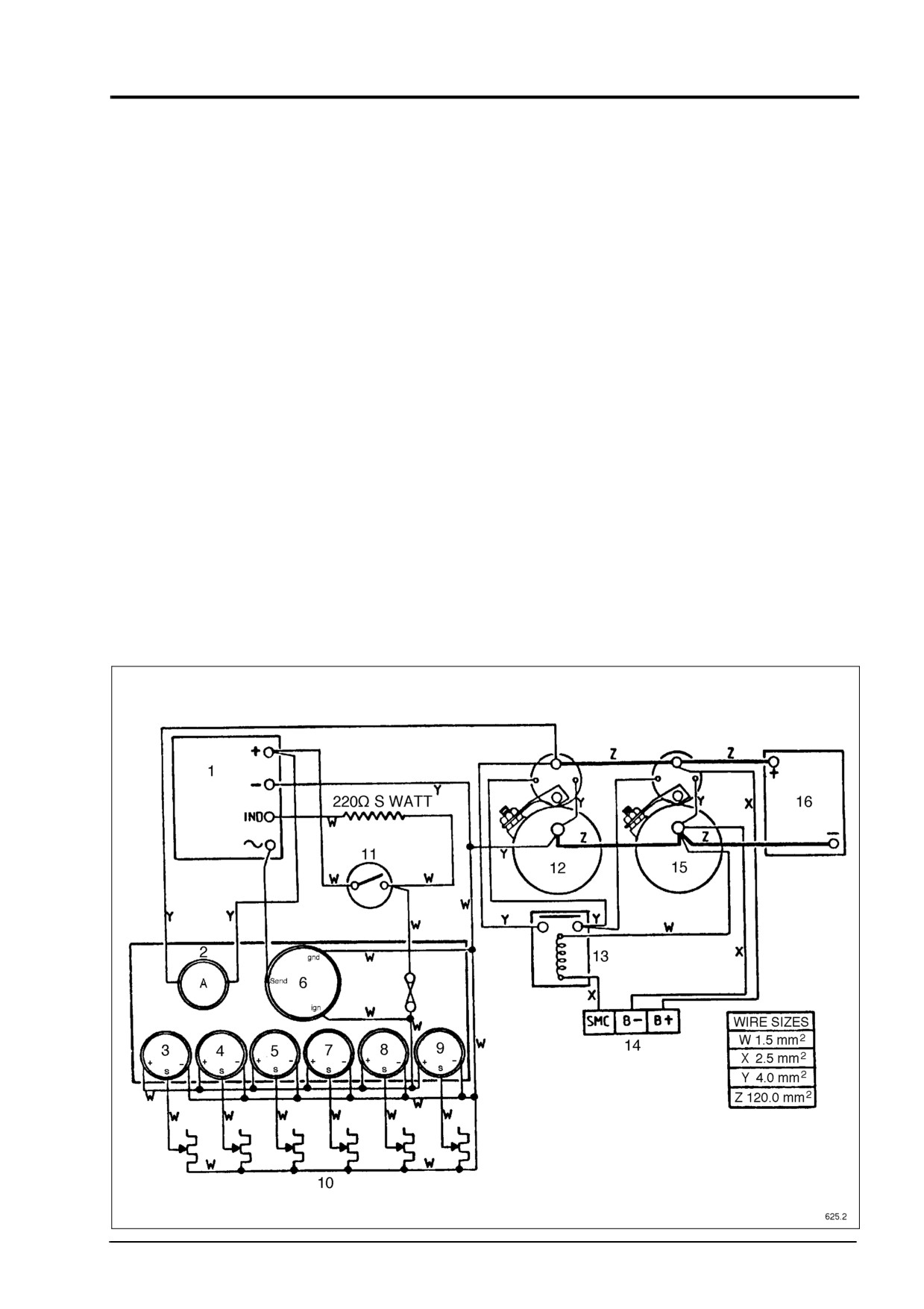
4012/16 (GAS) MINNOX ENGINE WIRING DIAGRAM STARTING CIRCUIT WITH
BUTEC STARTERS AND OPTIONAL INSTRUMENT PANEL
Key
(Fig. 36)
1. Charging alternator
2. Ammeter
3. Oil press
4. Oil temp.
5. Water temp.
6. Tacho
7. Oil press
8. Oil temp.
9. Water temp.
10. Gauge senders
11. Oil press switch
12. No. 1 Starter motor
13. Start relay
14. Engine terminal block
15. No. 2 Starter motor
16. 24 Volt Start batteries
Fig. 36
4012/16 Gas, February 1998
47
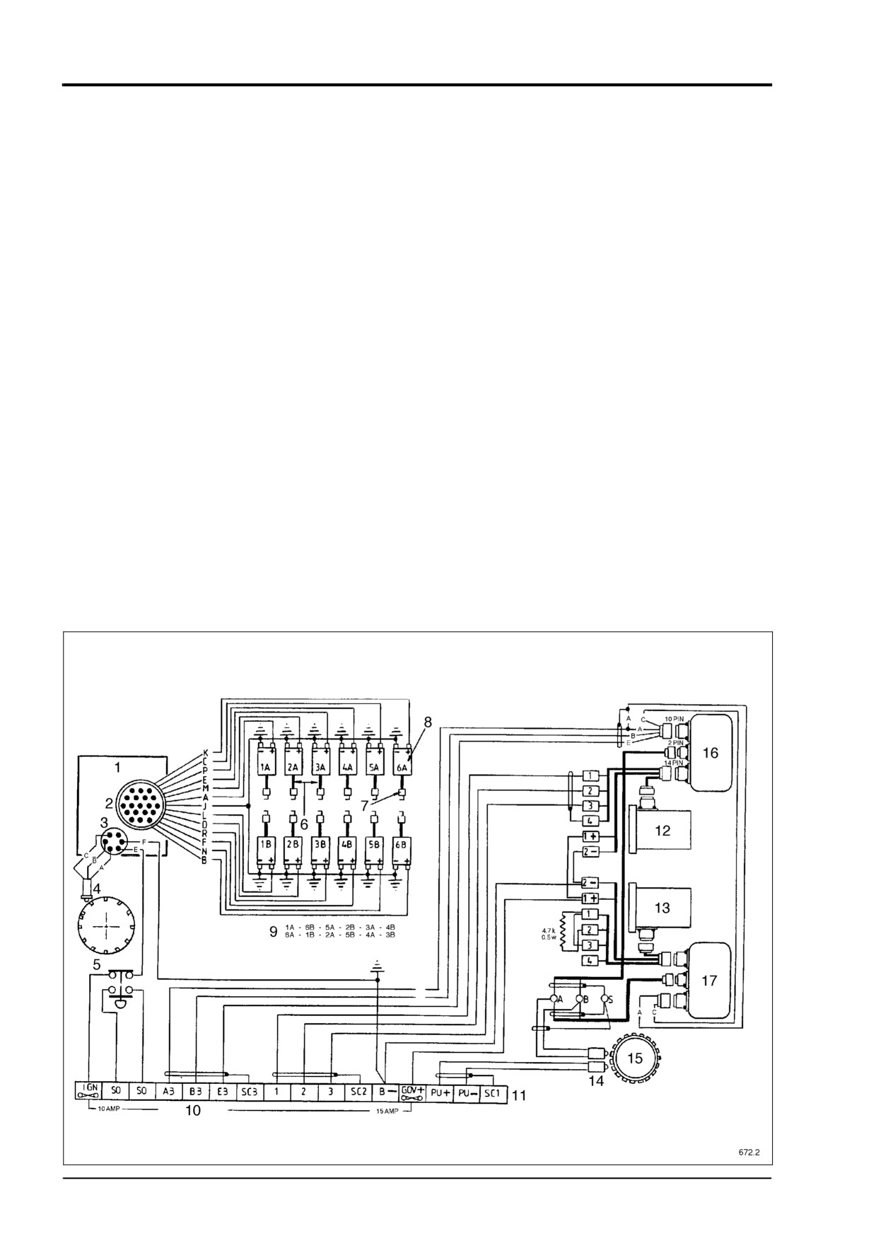
EARLY 4012 SERIES GAS IGNITION AND HEINZMANN WIRING SYSTEM
Key
(Fig. 37)
1. DISN Unit
2.
19 Pin plug
3.
6 Pin plug
4.
Pick-up
5.
Engine fitted emergency stop button
6.
H.T. Leads
7.
Spark plugs
8.
Ignition coils
9.
Firing order
10. Fused terminals
11. Engine fitted terminal box
12. Heinzmann actuator 'A' bank left
13. Heinzmann actuator 'B' bank right
14. Magnetic pick-ups
15. Engine flywheel
16. Heinzmann control box 'A' bank left
17. Heinzmann control box 'B' bank right
Fig. 37
48
4012/16 Gas, February 1998
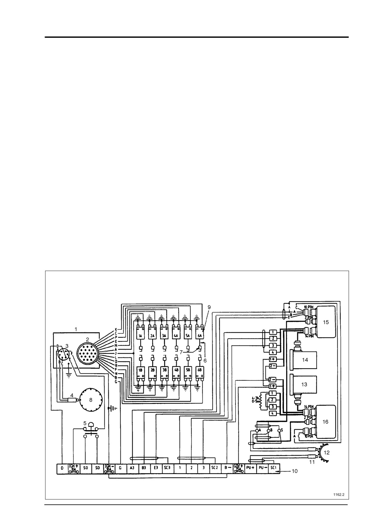
CURRENT 4012 SERIES GAS IGNITION AND HEINZMANN WIRING SYSTEM
Key
(Fig. 38)
1. DISN Unit
2.
19 Pin plug
3.
6 Pin plug
4.
Pick-up
5.
Engine fitted emergency stop button
6.
H.T. Leads
7.
Spark plugs
8.
Magnetic disc
9.
Ignition coils
10. Terminal box
11. Magnetic pick-up
12. Engine flywheel
13. Heinzmann actuator 'A' bank
14. Heinzmann actuator 'B' bank
15. Heinzmann control box 'B' bank right
16. Heinzmann control box 'A' bank left
Fig. 38
4012/16 Gas, February 1998
49
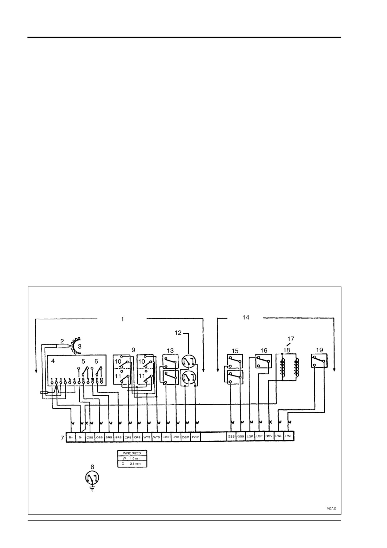
4012/16 (GAS) MINNOX ENGINE WIRING DIAGRAM OF STANDARD PROTECTION
PACK AND OPTIONAL BRITISH GAS COUNCIL PROTECTION EQUIPMENT
Key
17. Gas solenoid valves not normally
(Fig. 39)
supplied by Perkins can be four off
1. Standard fitted equipment
depending on gas pipe work arrangement
2. Magnetic pick-up
18. Energised to run gas line
solenoid
3. Engine flywheel
valves
4. Two switch speed unit
19. Low water level fault switch
5. Switch 2 over speed
6. Switch 1 speed 600 rpm
7. Engine terminal box
8. NOTE:
1. High manifold gas pressure and gas
spitback can be on the same fault
channel.
2. Manifold out of balance switch
gauges can be earth return type.
9. Left/right banks engine fault switches.
10. Water temp.
11. Oil press
12. Left/right banks manifold out of balance
switch gauges
13. Left/right banks high manifold gas
pressure fault switches
14. Optional equipment
15. Left/right banks gas spitback fault
switches
16. Low gas pressure fault switch
Fig. 39
50
4012/16 Gas, February 1998
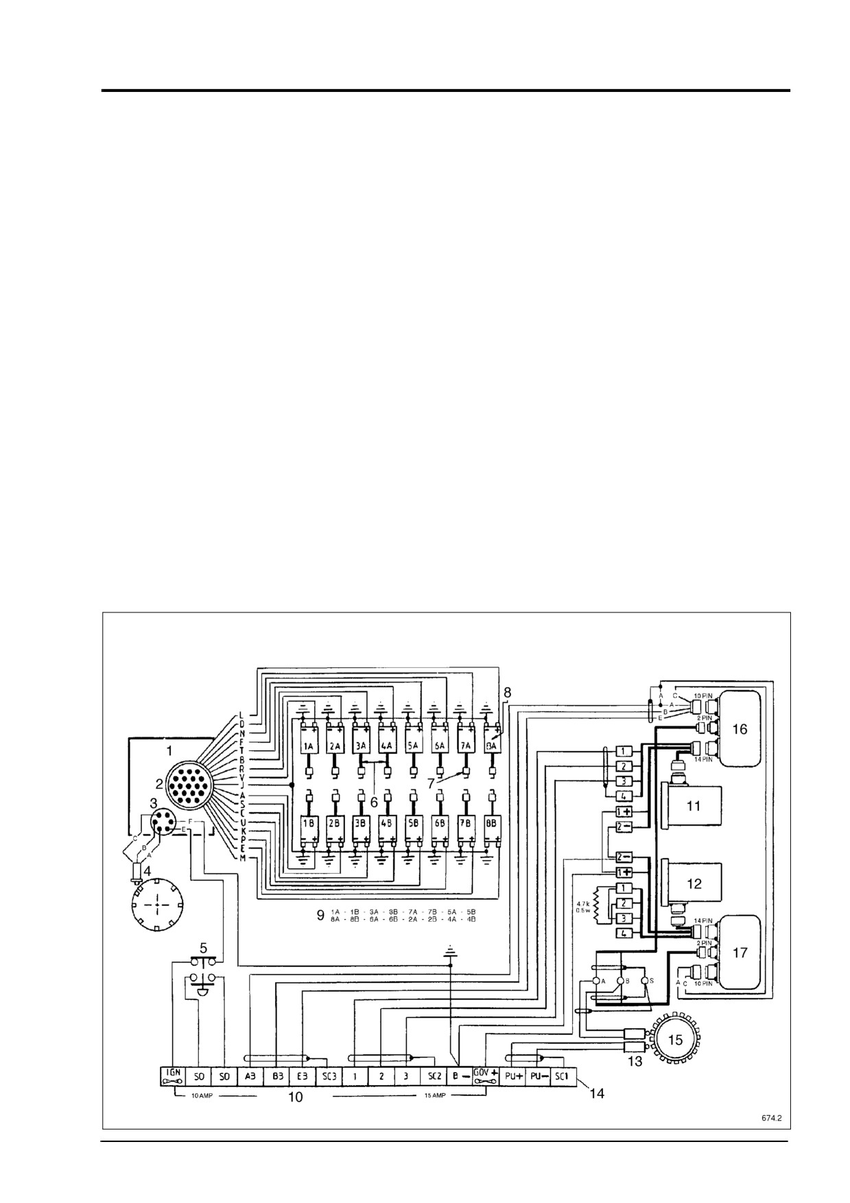
EARLY 4016 SERIES GAS IGNITION AND HEINZMANN WIRING SYSTEM
Key
(Fig. 40)
1.
DISN Unit
2.
19 Pin plug
3.
6 Pin plug
4.
Pick-up
5.
Engine fitted emergency stop button
6.
H.T. Leads
7.
Spark plugs
8.
Ignition coils
9.
Firing order
10. Fused terminals
11. Heinzmann actuator 'A' bank left
12. Heinzmann actuator 'B' bank right
13. Magnetic pick-ups
14. Engine fitted terminal box
15. Engine flywheel
16. Heinzmann control box 'A' bank left
17. Heinzmann control box 'B' bank right
Fig. 40
4012/16 Gas, February 1998
51
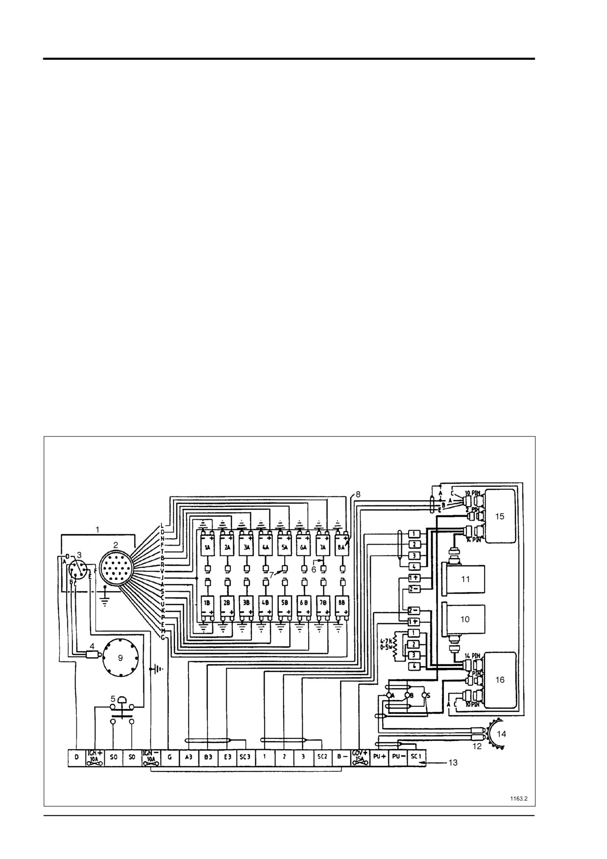
CURRENT 4016 SERIES GAS IGNITION AND HEINZMAN WIRING SYSTEM
Key
(Fig. 41)
1. DISN Unit
2.
19 Pin plug
3.
6 Pin plug
4.
Pick-up
5.
Engine fitted emergency stop button
6.
HT Leads
7.
Spark plugs
8.
Ignition Coils
9.
Magnetic Disc
10. Heinzmann actuator 'A' bank left
11. Heinzmann actuator 'B' bank right
12. Magnetic pick-ups
13. Engine fitted terminal box
14. Engine flywheel
15. Heinzmann control box 'A' bank left
16. Heinzmann control box 'B' bank right
Fig. 41
52
4012/16 Gas, February 1998