Tachometer ТХ01-RS. User guide
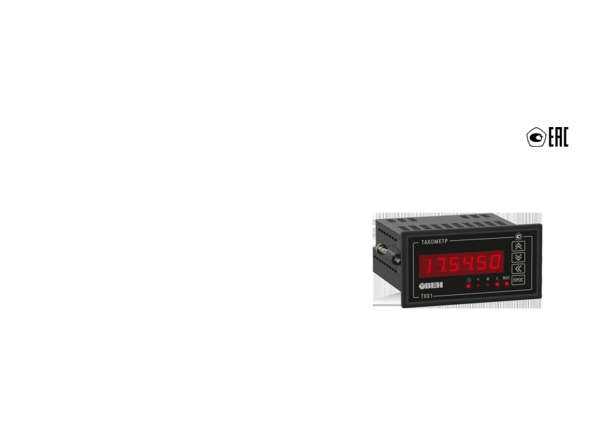
ТХ01-RS
Tachometer
User guide
Contents
Warning notice system
5
Introduction
6
Abbreviation
7
Characters on display
7
1 Purpose and functions
8
2 Specification
9
2.1 Technical data
9
2.2 Operating conditions
13
3 Safety
14
4 Installation
15
4.1 Installation of device in housing Н
15
4.2 Installation panel-mounting device in Щ2 housing
17
5 Connection
19
5.1 Wiring recommendations
19
5.2 Getting Started
20
5.3 Terminal block contacts assignments
21
5.4 Connection of switching devices and sensors
21
5.5 Connecting load to the outputs
23
5.5.1 Analog outputs
24
5.5.2 Digital output
27
6 Operation
28
6.1 Principle of operation
28
6.2 Control and indication
30
3
6.3 Switch on and operation
33
6.3.1 Tachometer mode
34
6.3.2 Operating time counter
36
7 Configuration
37
7.1 Setup sequence
37
7.2 Calibration mode setting
41
7.3 Output settings
43
7.4 Configuring the device from a PC
48
8 Maintenance
50
8.1 Maintenance
50
8.2 Calibration
50
9 Marking
53
10 Packaging
53
11 Transportation and storage
54
12 Scope of delivery
54
13 Warranty
55
Appendix A Device parameters
56
Appendix B Possible malfunctions and solutions
64
4
Warning notice system
Explanation of the symbols and keywords used:
DANGER
DANGER indicates an imminent dangerous situation that will result in death or serious
injuries if not prevented.
CAUTION
CAUTION indicates a potentially dangerous situation that could result in minor injuries.
NOTICE
NOTICE indicates a potentially dangerous situation that could result in damage to property.
NOTE
NOTE indicates helpful tips and recommendations, as well as information for efficient and
trouble-free operation.
5
Introduction
This document provides detailed information about the operation principle, design, configuration,
installation and maintenance of the tachometer ТХ01-RS, hereinafter referred to as the Device.
Connection, setup and maintenance should be made only by qualified specialists after reading this
manual.
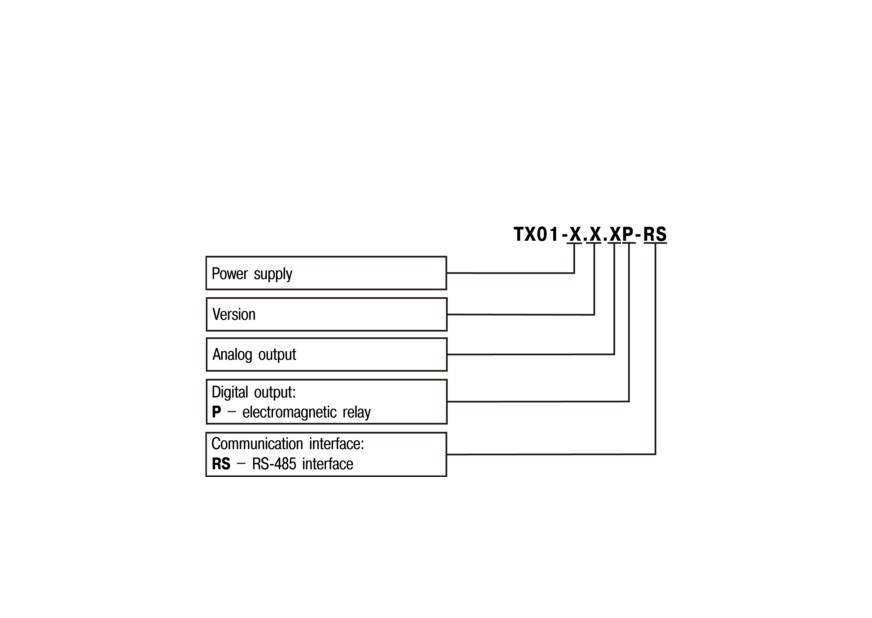
The device is produced in various modifications, that are encrypted in code of full conventional
designation.
Power supply:
224 - 90…264 V AC or 20…34 V;
24 - 10,5...30 V DC.
6
Construction type:
H - wall-mounting housing;
Щ2 - panel-mounting housing.
Analog output:
И - DAC «parameter-4…20 mA»;
У - DAC «parameter-0…10 V»;
not specified - without analog output
Example of ordering key: ТХ01-224. Н. ИР-RS. The device in case Н is to be delivered, with a power
supply of 224 V, an analog output of type И, a discrete output of type P and an RS-485 interface.
Abbreviation
DAC - digital-to-analog converter.
PC - personal computer.
Characters on display
A
b
C
d
E
F
G
H
i
J
K
L
M
n
O
P
Q
r
S
t
U
V
W
X
Y
Z
A
b
C
d
E
F
G
H
i
J
K
L
M
n
O
P
Q
r
S
t
U
V
W
X
Y
Z
7
1 Purpose and functions
The device is designed for:
• measuring and automatically controlling the speed of shafts and parts of mechanisms, as well as
other physical values, that can be converted into a value inversely proportional to the duration of
the interval between the edges of the pulses coming from the primary transducer (sensor);
• measuring the operating time of the connected equipment or other quantities that can be
converted into the duration of the interval during which a control signal is supplied to the input of
the device;
• control of external equipment in accordance with the customizable logic of the device (if there is an
output).
Device is used in control and regulation systems when performing various technological processes in
industry, agriculture and other sectors of the national economy, in particular for the automation of diesel
systems.
8
2 Specification
2.1 Technical data
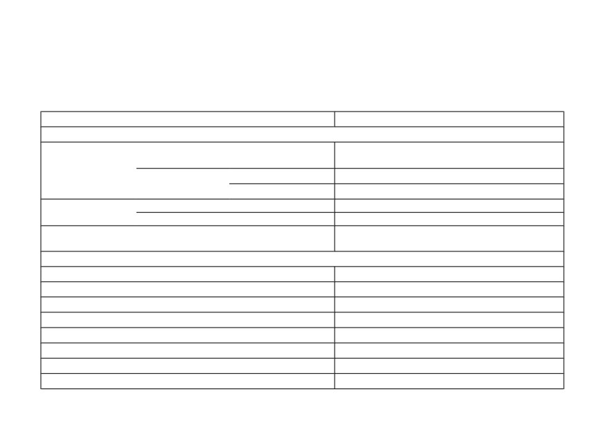
The main technical data of the device are presented in Table 2.1.
Table 2.1 - Device features
Description
Value
Power supply
Power supply
from AC mains
ТХ01-224.Х.ХР-RS
90 … 264 V AC, 47 … 63 Hz
(nominal values: 110 V, 220 V or 240 V)
from DC mains
ТХ01-224.Х.ХР-RS
20 … 34 V DC (nominal value: 24 V)
ТХ01-24.Х.ХР-RS
10.5 … 30 V DC (nominal values: 12 V, 24 V)
Power
ТХ01-24.Х.ХР-RS
8W
consumption, max.
ТХ01-224.Х.ХР-RS
10 VA
2400; 4800; 9600; 14400; 19200; 28800; 38400;
Baud rate for RS-485
57600; 115200 bit/s
Inputs
Number of inputs
2
Maximum input current
10 mA
Voltage of Logical 1
from 12 to 30 V
Voltage of Logical 0
from 0 to 4 V
Current of Logical 1, min.
3 mA
Current of Logical 0, max.
1.5 mA
Maximum input voltage
30 V
Pulse duration at counting input, min.
10 µs
9
Table 2.1 (continued)
Description
Value
Duration of the signal at operating time counter, min.
300 ms
Maximum pulse repetition rate at pulse counter, min.
2500 Hz
Minimum pulse repetition rate at pulse counter, min.
0.2 Hz
Filtering the input signal by the duration of the pulses (pauses)
10…999999 µs
Internal power supply
Nominal DC voltage
24 V DC
Maximum output current
50 mA
Instability of output supply voltage, max.
12 %
Pulsation level, max.
100 mV
Outputs
Electromagnetic relay (R)
Maximum load current (at 220 V, 50 Hz and cos φ > 0.4)
8A
Maximum DC load voltage
30 V
Analog output of type И
Output signal
from 4 to 20 mA
Load resistance
from 0 to 1300 Ω
DAC supply voltage
from 10 to 30 V
Accuracy, max.
0.5 %
Analog output of type У
Output signal
from 0 to 10 V
Load resistance, min.
2 kΩ
10
Table 2.1 (continued)
Description
Value
DAC supply voltage
from 10 to 30 V
Accuracy, max.
0.5 %
Housing
Dimensions
wall-mounted (Н)
105 × 130 × 65 mm
panel-mounted (Щ2)
96 × 48 × 100 mm
IP code
wall-mounted (Н)
IP44
panel-mounted (Щ2)
IP54 (front panel)
Device features
Speed value, n
rps
n=f
rpm
n = 60∙f
rph
n = 3,600∙f
custom units (USER mode)
n = F∙10 -FdP
Input frequency, f
0.2 … 2500 Hz
Multiplier, F
from 0.0001 to 999
from 0 s to 99 h 59 min 59 s
Measurement ranges of time intervals
from 100 h 00 min to 9999 h 59 min
from 10000 h to 9999 days 23 h
n¼
5
103 nmeas
þC
Accuracy in «Tachometer» mode (rps, rpm, prh, specified units)
where nmeas is the measured value in the selected
display dimension (rps, rpm, rph, USER mode);
11
Table 2.1 (continued)
Description
Value
C is the unit of the smallest digit of display taking
into account the position of the decimal point (rps,
rpm, rph)
Depending on the position of the decimal point, C
is:
• 1 (at dP = 0);
• 0.1 (at dP = 1);
• 0.01 (at dP = 2);
• 0.001 (at dP = 3);
• 0.0001 (at dP = 4)
¼
5
103meas þ C
where τmeas is the duration of the time interval
measured by the device (s);
The limit of permissible absolute error of measurement of time
C is the unit of the least discharge of the
intervals (s, min, h)
measuring range.
Depending on the measuring range, C is equal to:
• 1 s (for range from 0 s to 99 h 59 min 59 s);
• 1 min (for the range from 100 h 00 min to
9999 h 59 min);
• 1 h (for the range from 10000 h 00 min to
9999 days 23 h)
Weight, max.
0.5 kg
Average service life
12 years
Mean time between failures
75000 h
12
By operational completeness, the device belongs to second-order products.
Isolation of live circuits of the device meets the requirements of GOST R 52931.
The electrical insulation resistance of the current-carrying circuits of the device among themselves in
accordance with GOST R 52931 is as follows:
• 20 MΩ (under normal environmental conditions);
• 5 MΩ (at the upper temperature value of the operating conditions);
• 1 MΩ (at the upper value of the relative humidity of the operating conditions).
2.2 Operating conditions
The device is designed for operation in the following conditions:
• closed explosion-proof rooms without aggressive vapors and gases;
• ambient temperature: from -20 to +70 °С;
• relative humidity: max. 95 % (at ≤ 35 °C, non-condensing);
• atmospheric pressure: from 84 to 106.7 kPa.
In terms of resistance to mechanical influences during operation the device corresponds to group of
performance N2 in GOST R 52931.
In terms of resistance to electromagnetic influences (interference resistant), the device corresponds to
class A equipment according to GOST 51522.
By the level of radiation of radio interference (interference emissions), the device corresponds to class
B equipment according to GOST 30804.6.4.
NOTICE
Requirements in terms of external influencing factors are mandatory as related to safety
requirements.
13
3 Safety
CAUTION
There is a life-threatening voltage of up to 250 V on the terminal block of ТХ01-224.Х.ХР-RS.
Any connections to the device and maintenance work should be carried out only when the
device power is turned off.
By the method of protection from electric shock the device corresponds to class II according to
GOST12.2.007.0-75.
While operating, maintaining and checking, it is necessary to comply with GOST 12.3.019-80, Rules of
technical operation of electric installations of consumers and Safety code for operation of electric
installations of consumers.
Do not allow moisture to contact the output connector and the internal electrical elements of the device.
It is forbidden to use the device in corrosive environments containing in the atmosphere of acids, alkalis,
oils, etc.
14
4 Installation
4.1 Installation of device in housing Н
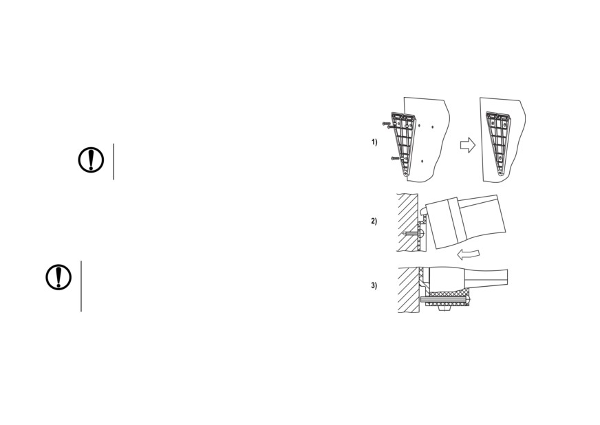
To connect Device:
1. Fasten the bracket with three M4 × 20 screws on
the surface intended for mounting the Device (see
Figure 4.2).
NOTICE
Bracket mounting screws are not
included.
2. Hook the fixing bracket from the back panel of
device to the upper edge of the wall bracket.
3. Attach device to the bracket with the supplied
screw.
Demount the device in the reverse order.
NOTICE
Remove the cover before wiring. Fasten the
base of the device to the bracket with a
supplied screw.
Figure 4.1 - Installation of wall-mounting
device
15
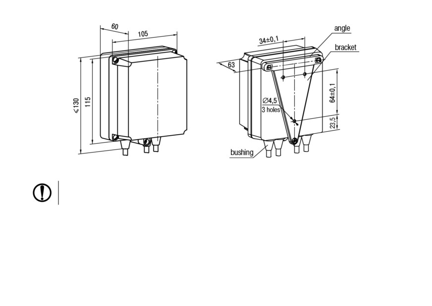
Figure 4.2 - Dimensions of H housing
NOTICE
The bushings need to be cut in accordance with the diameter of the lead-in cable.
16
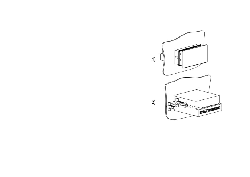
4.2 Installation panel-mounting device in Щ2 housing
To connect Device:
1. Prepare a place for mounting on the control panel
(see Figure 4.4).
2. Install the gasket on the frame of the device to
ensure degree of protection IP54.
3. Insert the device into a specially prepared hole on
the front of the control panel.
4. Insert the supplied retainers into holes on the
sides of the device.
5. Tighten supplied screws M4 x 35 in the holes of
each retainer so that the device is firmly pressed
to the front of the control panel.
Demount the device in reverse order.
Figure 4.3 - Installation of panel-
mounting device
17
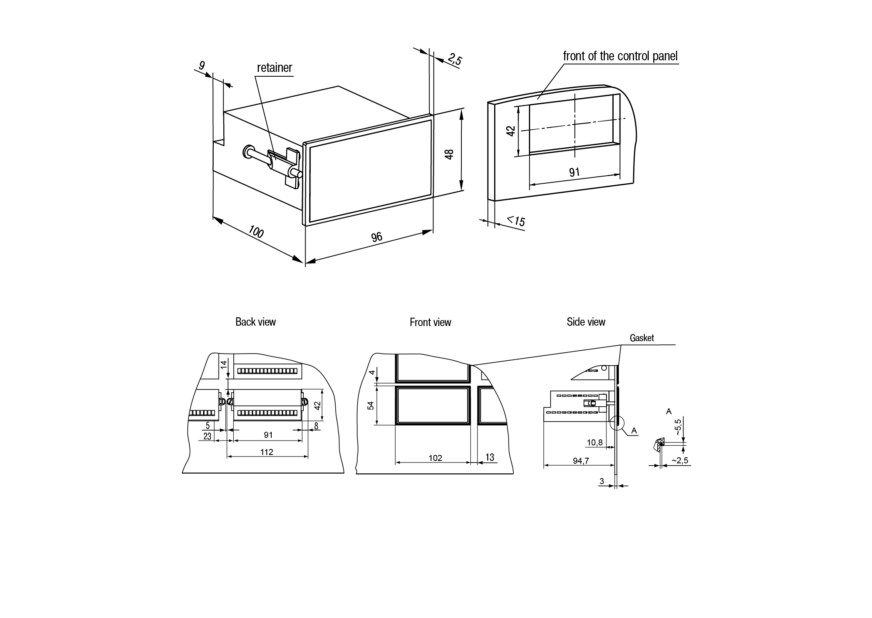
Figure 4.4 - Dimensions of Щ2 housing
Figure 4.5 - The device in Щ2 housing mounted in the control panel thickness of 3 mm
18
5 Connection
5.1 Wiring recommendations
To ensure the reliability of electrical connections it is recommended to use copper stranded cables, the
ends of which should be carefully cleaned and tinned. Otherwise use cable lugs before connection.
Cable conductors should be stripped so that their bare ends do not protrude beyond the terminal strip
after connecting to the device. The cable cross section must be not more than 1 mm2.
General requirements for connection lines:
• During the cabling, communication lines that connect the Device with sensors must be isolated to
a separate circuit (or several circuits) and placed separately from power cables or other sources
of high-frequency and impulse interferences;
• To protect the Device inputs from the effects of industrial electromagnetic interference, the
communication lines between Device and sensors should be shielded. Special cables with
shielding or grounded steel pipes of suitable diameter can be used. The cable shielding should be
connected to the functional ground terminal (FE) in the control panel;
• Network interference filters should be installed in the power supply lines;
• Spark-fighting filters should be installed in the switching lines of power equipment.
When installing the system in which the Device operates, you should follow the rules for effective
grounding:
• all grounding lines must be laid in Y-connected circuit, ensuring good contact with the grounding
element;
• all earthing circuits must be made with wires of the largest possible cross-section;
• it is forbidden to connect the device terminal "Common" with grounding lines.
19
5.2 Getting Started
DANGER
After unpacking the device, make sure that the device has not been damaged during
transportation.
If the device was kept for a long time at a temperature below minus 20 °С, then before turning it on and
starting work, it should be kept in a room with a temperature corresponding to the operating range for
30 minutes.
To connect the device:
1. Connect the Device to a power source.
CAUTION
Before applying power to the Device, check that the supply voltage and its level are
correct.
2. Connect primary transducers to the device inputs.
3. Apply power to the device.
4. Set up the device.
5. Make a test run of the device algorithm to verify that the settings are correct.
6. Power off the device.
7. Connect operating mechanisms to the device outputs.
20
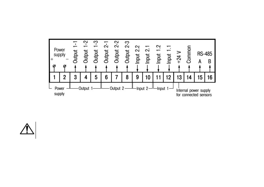
5.3 Terminal block contacts assignments
Screw terminals are located on the back wall (panel-mounting) or inside the device (wall-mounting). The
terminal block contacts assignment is shown in Figure 5.1.
Figure 5.1 - Terminal block contacts assignments
5.4 Connection of switching devices and sensors
CAUTION
Do not apply voltage to the device inputs (pins 9 - 12 of the terminal block) that is outside the
range from 0 to 24 V.
21
NOTICE
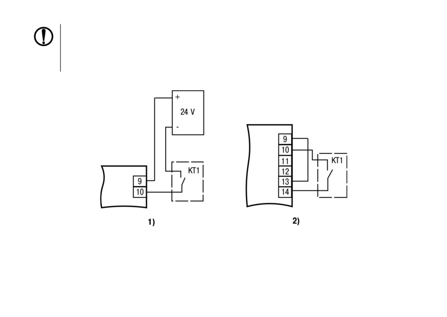
Pin 13 is an internal power supply, required for connecting of switching devices and sensors.
If the power consumption of the input devices exceeds the load capacity of the internal power
source (24 V), an external source with an output voltage of 12 to 34 V (recommended 24 V) is
required.
Scheme for connection of the switching devices to the inputs is shown in Figure 5.2.
Figure 5.2 - Connecting switching devices: 1) when the device is operating from an external
power source; 2) when the device is operating from an internal power source
The connection diagrams of passive sensors with an n-p-n-type transistor with an open collector output
are shown in Figure 5.3.
22
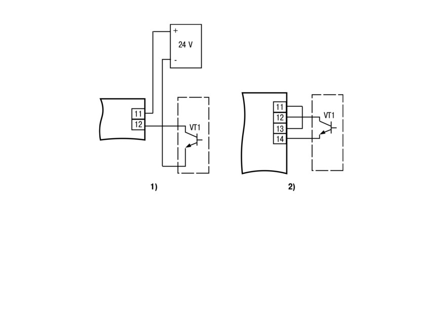
Figure 5.3 - Connection of passive sensors with n-p-n-output: 1) when the sensor is operating
from an external power source; 2) when the sensor is operating from an internal power source
5.5 Connecting load to the outputs
The device may not have outputs, have one analog or digital output or two outputs, one of which is
analog, and the second is digital.
23
CAUTION
The outputs are galvanically isolated from the circuit of the device.
It is possible to use an internal 24 V power supply to power the output, which is used to power active
sensors.
5.5.1 Analog outputs
The analog output can operate as a DAC in two modes: “parameter-current” (И) or “parameter-voltage”
(У).
For normal operation of devices with an analog output of type И, the DAC must be powered from an
independent DC source that provides galvanic isolation of the device’s electrical circuit and “connected
mechanisms”. The voltage of the power source is calculated by the formulas:
UPSmin UPS UPSmax
UPSmin ¼ 7:5 þ IDACmax Rload
UPSmax ¼ UPSmin þ 2:5
where UPS is voltage of the power source, V;
UPS min is the minimum allowable voltage of the power source, V;
UPS max is the maximum allowable voltage of the power source, V;
IDAC max is the maximum allowable current of DAC, mA;
Rload is load resistance of DAC, kΩ.
24
CAUTION
The USP value must be included in the allowable range of the supply voltage (from 10 to 36 V).
If for any reason the voltage of the DAC power supply exceeds the calculated value USP max, then the
limiting resistor should be connected in series with the load, the resistance of which is calculated by the
formulas:
Rlimitmin < Rlimitnominal < Rlimitmax
Rlimitmin ¼UPS UPSmax
IDACmax
Rlimitmax ¼UPS UPSmin
IDACmax
where Rlimit nominal is nominal value of the limiting resistor, kΩ;
Rlimit min is minimum permissible value of the limiting resistor, kΩ;
Rlimit max is maximum permissible value of the limiting resistor, kΩ;
IDAC max is the maximum allowable current of DAC, mA;
UPS is voltage of the source used to power the DAC, V.
An example of the connection to the output of type И with a power source and load is presented in
Figure 5.4.
25
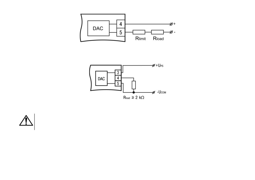
Figure 5.4 - Wiring of output of type И
An example of connection to the output of type У is shown in Figure 5.5.
Figure 5.5 - Wiring of output of type У
CAUTION
The load resistance Rload connected to the DAC must be at least 2 kΩ.
The voltage of the output power source should be not more than 30 V.
26
5.5.2 Digital output
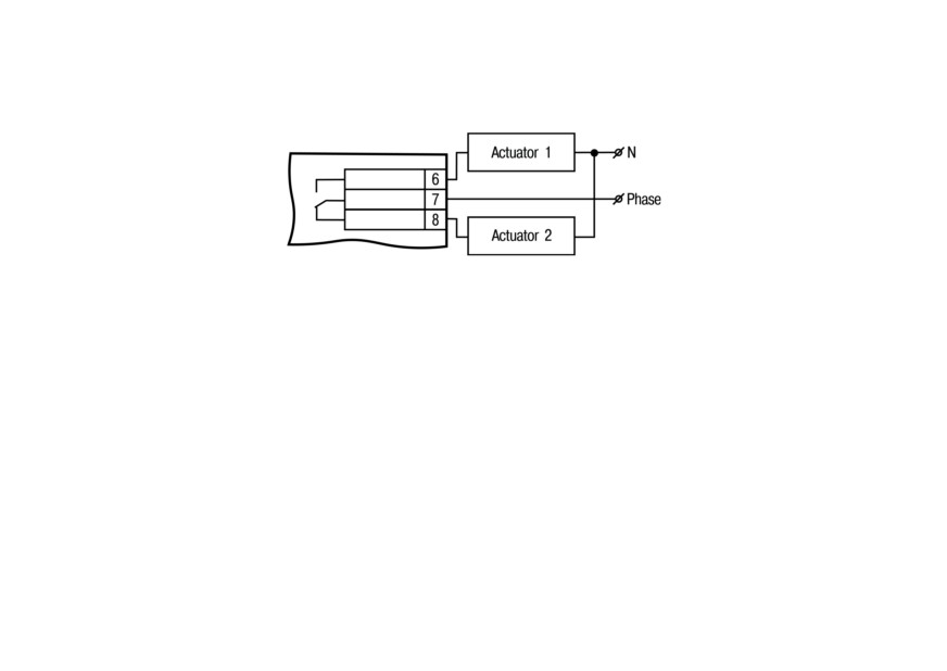
The digital output is an electromagnetic relay (type P) (see Figure 5.6). This output is used to control the
load (on / off) directly or through more powerful control elements, such as starters, solid state relays.
Figure 5.6 - Output wiring
27
6 Operation
6.1 Principle of operation
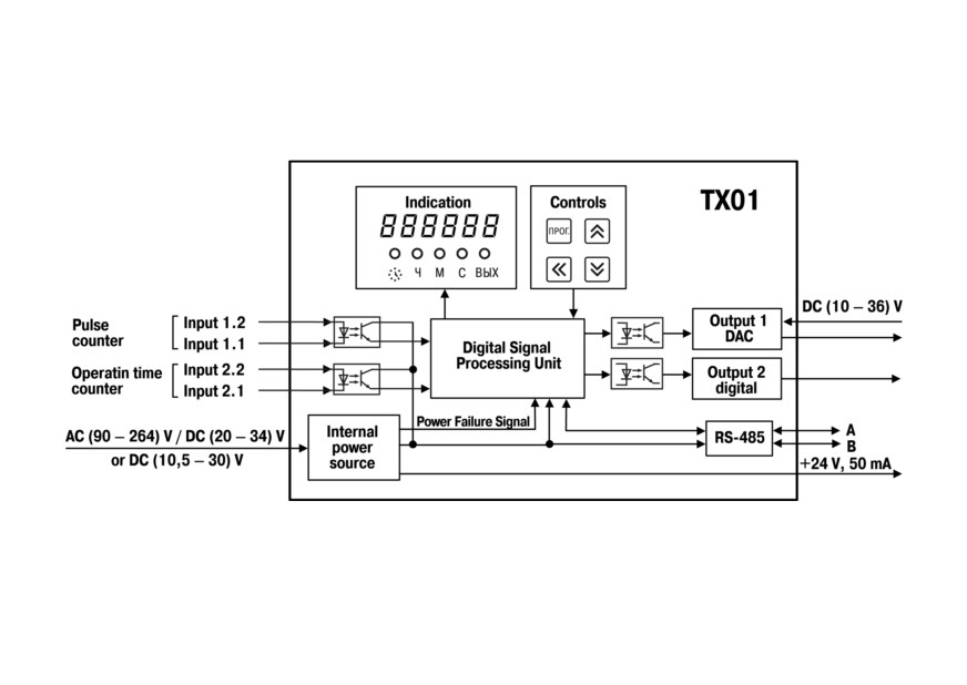
Functional diagram of the device is shown in Figure 6.1.
Figure 6.1 - Device operation
The device has two digital inputs for connecting sensors (pulse counter and operating time counter). To
the inputs of the device can be connected:
• sensors with output n-p-n-transistor with an open collector;
28
• sensors with a dry contact type output (reed switches).
The counting input of the device receives pulses from a sensor that controls one or more marks on the
motor shaft.
The levels of the input signals are converted and processed in the matching unit, after which they are
sent to the digital processing unit, where it occurs:
• filtering of input signals;
• measuring the instantaneous value of the shaft speed;
• measurement of operating time at the operating time counter;
• conversion of measured values into real physical quantities;
• scaling of values before their output to the display;
• generation of signals for controlling the outputs according to a specified algorithm.
NOTICE
The parameter-current/voltage conversion is carried out using the built-in output of a ten-digit
DAC. The signals obtained after the conversion can be used to register parameters.
Control unit includes buttons for entering parameters and controlling the operation of the device.
Display unit displays the measurement results or operating parameters on the indicators and shows
the device status using LEDs.
Internal power supply, depending on the version of the device (with AC or DC power), converts the
supply voltage for all units of the device and generates a signal indicating the loss of supply voltage. It
also generates a DC voltage to power the sensors connected to the inputs of the device.
Using the RS-485 interface, the device is connected to a PC, which makes it possible to set and edit the
configuration of the device, to monitor its current status and readings.
29
6.2 Control and indication
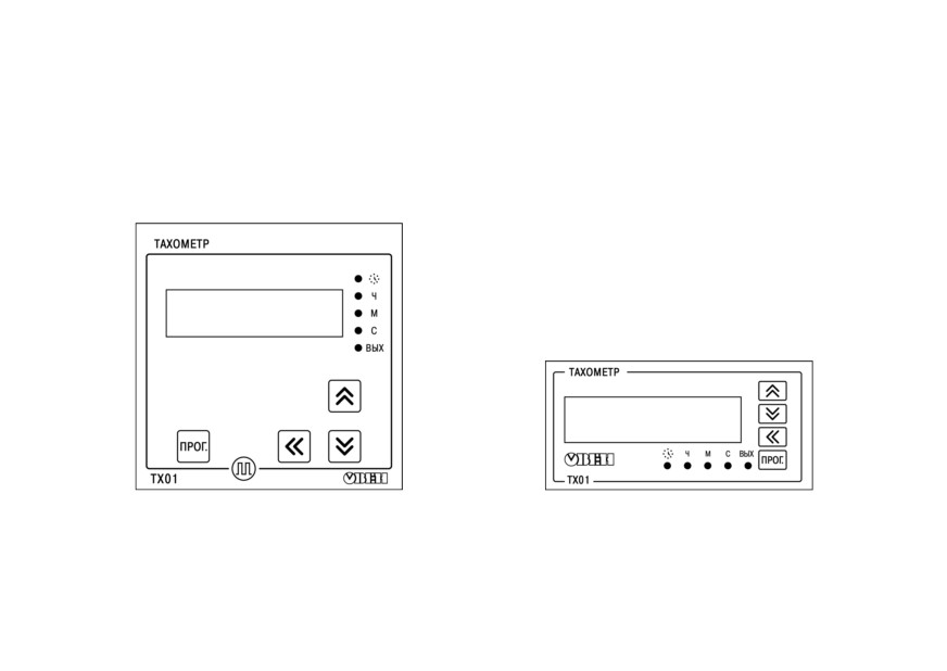
Elements of indication and control are located on the front panel of the device (see Figures 6.2 and 6.3):
• seven-segment six-digit display;
• five LEDs;
• four buttons.
Figure 6.2 - Front panel of the device in housing for Figure 6.3 - Front panel of the device in housing for
wall-mounting (Н)
panel-mounting (Щ2)
30
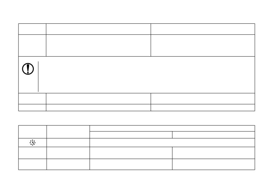
Table 6.1 - Display function
Operating
Displayed information
Refresh rate
mode
The current value of the pulse repetition rate
≤6s
obtained after filtering and averaging, taking into
(equal to the duration of the time interval between
Tachometer
account scaling at the measuring input of the
the leading edges of the pulses at the measuring
device
input of the device)
NOTICE
If the pulse repetition rate is less than 0.2 Hz or the pulse source disappears, then the last measured value
is displayed on the digital clock for 6 seconds, after which 0 will be highlighted.
If the pulse repetition rate exceeds the maximum value with a positive tolerance of 2 % (FrEQ × 1.02), then
the last measured value is displayed on the display for 6 seconds, after which the value recorded in the
FrEQ parameter flashes.
Operating
Operating time
1s
time counter
Setup
Parameter name and value
—
Table 6.2 - Assigning LEDs
Value
LED
State
Tachometer mode
Operating time counter
ON
Measurement of operating time is in progress
Range of operating time (DDDD.HH) -
Ч*
ON
Display scale - rph
from 10000 h to 9999 days 23 h
Range of operating time (HHHH.MM) -
М*
ON
Display scale - rpm
from 100 h to 9999 h 59 min
31
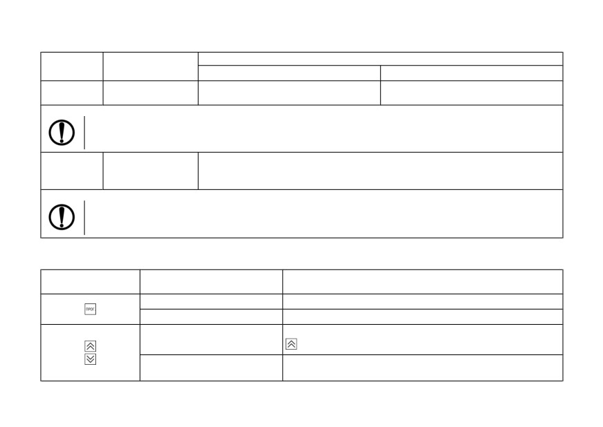
Table 6.2 (continued)
Value
LED
State
Tachometer mode
Operating time counter
Range of operating time (HH.MM.SS) -
С*
ON
Display scale - rps
from 0 to 99 h 59 min 59 s
NOTICE
* In USER mode, these LEDs are off.
• The digital output is enabled according to the selected logic.
ВЫХ
ON
• A digital signal corresponding to the maximum current / voltage value is applied
at the analog output
NOTICE
For devices with two outputs (discrete and analog), the LED glows in accordance with the logic of the
digital output.
Table 6.3 - Buttons Assignment
Operating mode of the
Button
Function
device
Operation
Switch to setup mode
Setup
Switch to editing a parameter value after selecting it
Switch to the display of operating hours counter values (hold
Operation
)
• Enter a password to change the settings (if it is not 0).
Setup
• View parameter values and edit them
32
Table 6.3 (continued)
Operating mode of the
Button
Function
device
Selecting an editable digit when changing a parameter value
Setup
and entering a password (used with the and buttons)
6.3 Switch on and operation
The device can perform following functions:
• tachometer;
• operating time counter.
The signals arriving at the counting input of the device are filtered. The filter is characterized by the
minimum allowable pulse and pause lengths (minImp parameter, ms). All pulses and pauses less than
the specified duration are perceived as bounce and ignored.
The recommended value for this parameter is calculated as follows:
where MaxFreqRele is the maximum frequency (up to 100 Hz) of switching a dry contact relay.
For input frequencies greater than 100 Hz, set minImp = 10 μs.
The principle of operation of this parameter is shown in Figure 6.4:
• 1: pulse duration and pause duration greater than minImp - the signal is passed through the
bounce protection system;
33
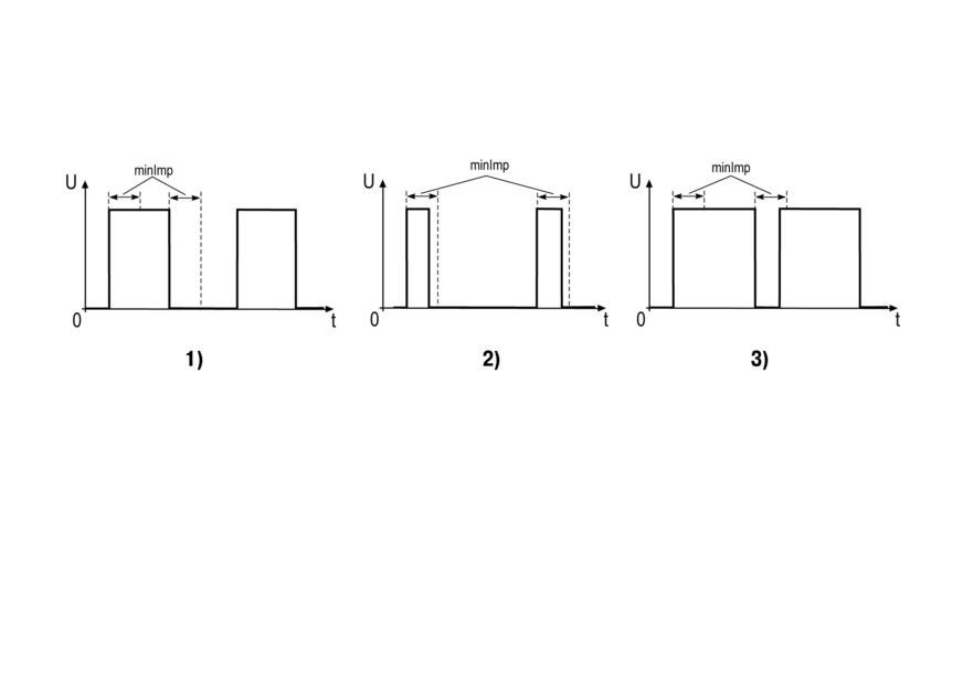
• 2: the pulse duration is less than minImp - the signal is not passed by the bounce protection
system;
• 3: the pulse duration is greater than minImp, but the pause duration is shorter than minImp - the
signal is not skipped by the chatter protection system.
Figure 6.4 - Parameter «minImp»
6.3.1 Tachometer mode
When performing the function of a tachometer:
• device measures the instantaneous value of the duration of the time intervals (T) between the
leading or trailing edges (in s);
• device calculates the value of N / T, where N is the value determined by the dimension of the
display of the measured value;
• device displays the obtained value taking into account the scaling factor.
34
The tachometer measurement interval is set by the dttA parameter in:
• rps (N = 1);
• rpm (N = 60);
• rph (N = 3600)
• custom values (N = F × 10-FdP, where F and FdP are variable parameters).
If F × 10-FdP < 1, the values dependent on dttA (FrEQ, UdAC, dPro, LOR, HIR, UdO, dU) can be less
than 1 (for example, 0.25) and displayed on the display as 0. This occurs because fractional display is
not supported. But in the operation of the device, values with a fractional part will be used.
The dttA value affects the upper and lower limits of the FrEQ parameter. That is, the limits are
recalculated in accordance with the coefficient N. For example, the values of the FrEQ parameter lie in
the range [1; 2500]. With the coefficient N = 60, the boundaries of the FrEQ parameter will be as
follows:
• lower limit: 1 × 60 = 60;
• upper limit: 2500 × 60 = 150000.
Counting results are shown on the display. Calculation units are displayed in the form of highlighting of
single LEDs (see Table 6.2 for details).
NOTICE
1. Rounding of the measurement results is carried out in a standard mathematical way, in a
big way. That is, if in a rounded digit a digit is more than or equal to 5, then one is
transferred to the next digit. If the measured value lies within 0.2 ... 0.5 Hz inclusively,
then a value of 1 is transmitted via Modbus to indicate the presence of a signal.
2. If the digit capacity is not enough to display the selected number of digits after the
decimal point, the device automatically shifts the number to the right.
35
An eighth-order moving average filter is used to damp the signal in the device. The MAV.L parameter
defines the minimum time (in seconds) for filling the filter buffer. Adding a new value to the buffer will be
done not earlier than in (MAV.L / 8) seconds. At input frequencies less than or equal to (8 /MAV.L), the
settling time of the input signal to the digital signal can be longer than MAV. L. By default, this filter is
enabled.
6.3.2 Operating time counter
The device counts the operating time if the signal level on the operating time counter reaches a logical
1. When the device performs this function, the LED lights up.
To see the current operating time on display, press and hold the button
. If you release this button, the
display returns to the tachometer reading.
The measured operating time is shown on the display (see Table 6.1 for details). If the current range is
exceeded, the device automatically sets the next display range of the measurement results. The
maximum value of the operating time takes values from 1 s to 9999 days 23 hours.
For devices with discrete output, it is possible to set the limit values of the operating time, upon reaching
which the output is switched on.
36
7 Configuration
7.1 Setup sequence
The Setup mode is intended for viewing and editing the device parameters. New parameters are saved
to non-volatile memory of the device.
To enter the setup mode, press and hold the button for at least 2 seconds.
Using
,
and enter the password, and then press and
. If the password is 0 (default), press
NOTICE
If you forgot your password, you can enter the settings mode using the password 1098!
Further password changes are available only on the RS-485 network.
If no button operations are performed within 2 minutes:
• when editing a parameter, the device automatically restores its value and returns to the parameter
viewing mode;
• when setting the parameter, the device automatically returns to tachometer mode.
Device settings and the possible values of each of the parameters are presented in Figures 7.1- 7.4
and in Appendix A.
NOTICE
Upon entering the settings menu, the device does not stop functioning in the operating mode
(it continues to measure the time interval between pulses, counts the operating time, controls
the operation of the output).
37
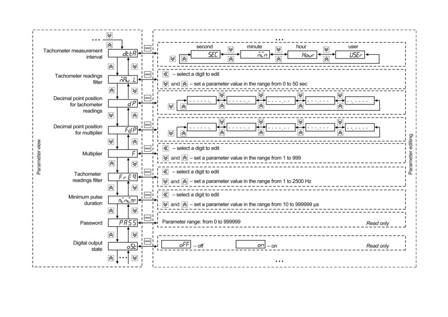
Figure 7.1 - Configuration menu
38
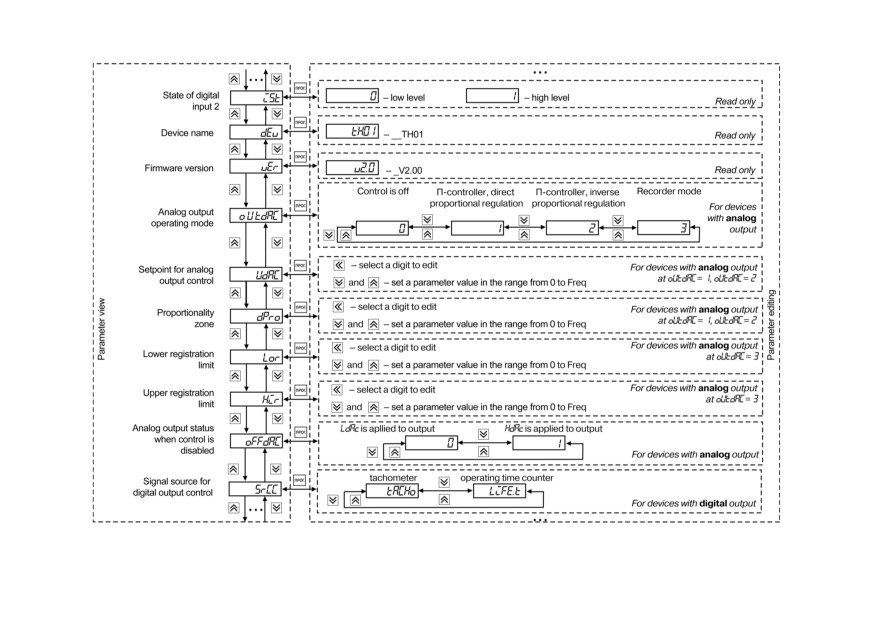
Figure 7.2 - Configuration menu (continued)
39
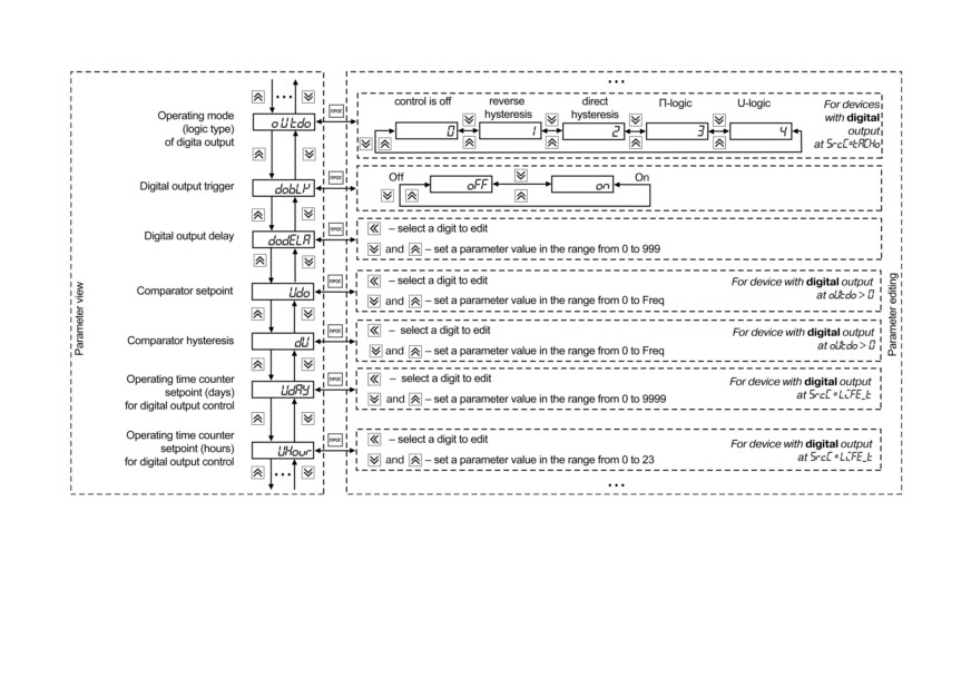
Figure 7.3 - Configuration menu (continued)
40
Figure 7.4 - Configuration menu (end)
7.2 Calibration mode setting
To enter the calibration mode, press and hold the and buttons for at least 2 seconds.
Using
,
and
buttons enter the password, and then press
and
. If the password is 0
(default), press
41
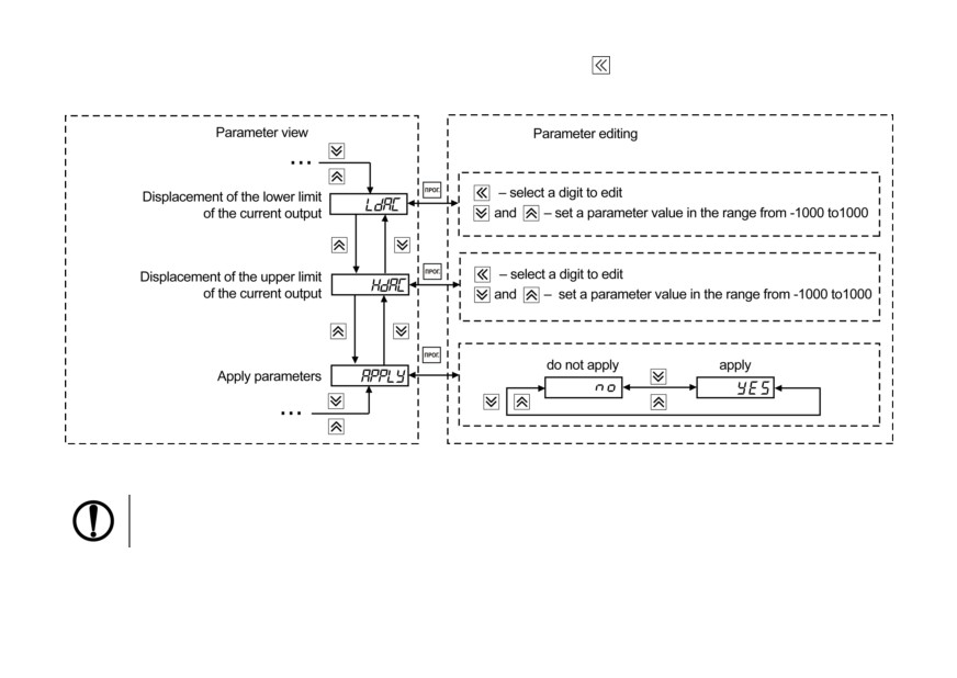
To exit the menu in the parameter viewing mode, press the button
The calibration parameters and the display of the possible values are shown in Figure 7.5.
Figure 7.5 - Calibration menu
NOTICE
For calibration, the value of the oUtdAC parameter must be other than 0.
42
7.3 Output settings
Device digital output (type P) functions as a comparison device (comparator).
The input value of the comparison device:
• tachometer measurement result (SrcC = tACHo) - control mode is selected using the oUtdo
parameter;
• measured value of the operating time (SrcC = LiFE_T) - the output is switched on when the
setpoint is reached to control the digital output for the operating time UdAY, UHour, UMin, USEc.
When the output is turned on, the ВЫХ LED lights up.
It is possible to work according to one of the following types of logic (see Figures 7.6 and 7.7):
• reverse hysteresis (oUtdo = 1) - output turns on at values Fcurrent > (U+Δ) and turns off at values
Fcurrent < (U-Δ);
• direct hysteresis (oUtdo = 2) - output turns on at values Fcurrent < (U-Δ) and turns off at values
Fcurrent > (U+Δ);
• П-shaped logic (oUtdo = 3) - output is turned on at values (U-Δ) < Fcurrent < (U+Δ);
• U-shaped logic (oUtdo = 4) - output is turned on with the values Fcurrent < (U-Δ) and Fcurrent > (U +
Δ).
43
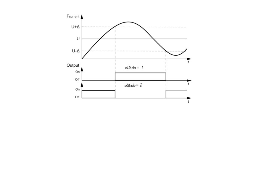
Figure 7.6 - Types of logic (reverse and direct hysteresis) when the output operates as a
comparator
44
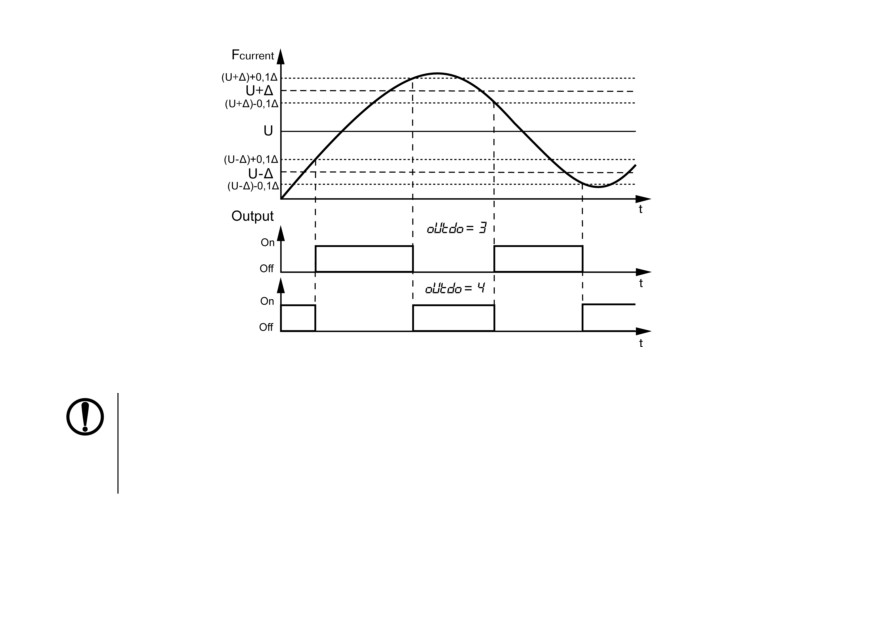
Figure 7.7 - Types of logic (П- and U-shaped) when the outputs operates as a comparator
NOTICE
1. With П- or U-shaped logic, to suppress bounce during switching, there is an additional
hysteresis of operation of 5 % of the range between the limits (2Δ) (see Figure 7.7).
2. When the pulse repetition rate at the counting input is more than FrEQ, the value equal
to the value calculated for FrEQ is set at the output.
Recommendations for setting the output:
• set oFFdo = 0 and oUtdo = 0;
45
• specify values in Udo and dU. It is recommended that Udo, dU, the upper and lower limits do not
go beyond 0 and FrEQ;
• set the desired output logic (oUtdo).
Digital output control is disabled when oUtdo = 0. The output status is set using the oFFdo parameter.
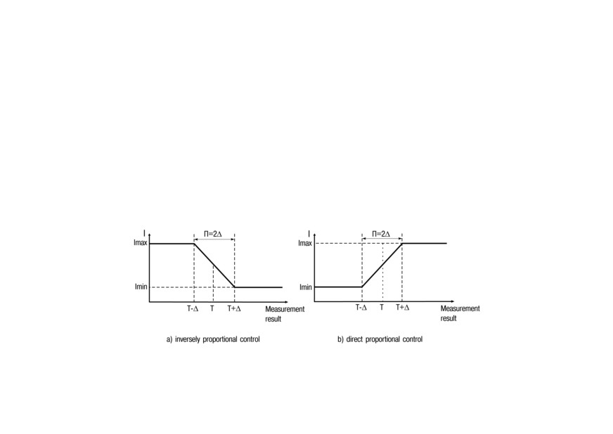
Analog output of the device (types И, У) functions as a П-controller and a recorder. The operation
mode of the analog output is set using the oUtdAC parameter.
When the output operates as a П-controller, the current value of the measured value is compared with
the preset setpoint (UdAC parameter) and the output signal is from 4 to 20 mA (for type И) or 0 to 10 V
(for type У) proportional to the deviation. The direct proportionality zone is set by the parameter Δ
(dPro). The output signal is generated in accordance with the regulator characteristic set in the oUtdAC
parameter, either in direct proportion (1) or inversely proportional (2) regulation law. Graphs explaining
the principle of forming the control current and voltage of the П-controller for both characteristics are
shown in the Figures 7.8 and 7.9.
Figure 7.8 - Generating of the output signal in the П-controller mode (output of type И)
46
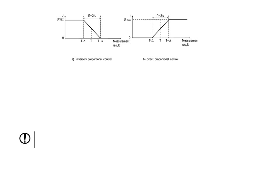
Figure 7.9 - Generating of the output signal in the U-controller mode (output of type У)
When the output works as a recorder (oUtdAC = 3), the following occurs:
• comparing the measured value with the set values of the lower limit of the recording range and the
value of the entire recording range;
• issuing an analog signal to the corresponding output in the form of a current from 4 to 20 mA (for
output type И) or voltage from 0 to 10 V (for output type У), which can be fed to a recorder or other
recording device.
The principle of generating the output signal is shown in Figures 7.10 and 7.11. When the output is
working as a recorder, the lower and upper limits of registration should be set in the Lor and Hir
parameters.
NOTICE
When the measured value goes beyond the recording range, the error level is set at the output:
20.2 mA (for type И output), more than 10.5 V (for type У output).
When oUtdAC = 0, the operation control of the analog output is disabled. The output status is set by
oFFdAC parameter.
47
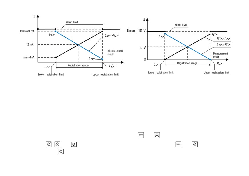
Figure 7.10 - Principle of generating the output signal Figure 7.11 - Principle of generating the output signal
in the recorder mode (output of type И)
in the recorder mode (output of type У)
7.4 Configuring the device from a PC
To configure the device with a PC, communication interfaces RS-485 is used. The device supports two
communication protocols: MODBUS RTU and MODBUS ASCII. Addresses, names and lengths of the
device parameters are given in Appendix A.
To go to the device settings from a PC, press and hold the and buttons for at least 2 seconds.
Then use the
,
and buttons to enter the password, and then press
and
. If the password
is 0 (default), press
48
To exit the menu in the parameter viewing mode, press the button
Settings for communicating with a PC and displaying on the digital indicator the possible values of each
of the parameters are presented in Figure 7.12.
Figure 7.12 - PC communication settings
49
8 Maintenance
8.1 Maintenance
Safety measures (see Section 3) should be observed during the maintenance.
Maintenance of the device has to be carried out at least once in 6 months and includes the following
procedures:
• checking the mounting of the device;
• checking the screw connections;
• removing dust and dirt from the terminal board of the device.
8.2 Calibration
Calibration is intended to restore the metrological characteristics of the device in case of their change
after prolonged use or repair work and consists in selecting the minimum and maximum values of the
output signal.
CAUTION
Calibration of the device should be carried out only by qualified specialists of metrological
services.
Calibration is carried out only for analog outputs. To do this:
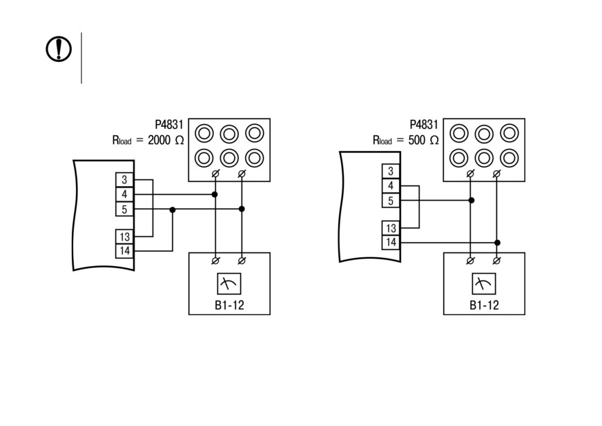
• connect the load (Rload) and a voltmeter to the output according to Figures 8.1(for output of type У)
and 8.2 (for output of type И);
• apply power to the device.
50
NOTICE
As Rload, you can use the resistance box P4831 or similar with an accuracy class of not more
than 0.05, and as a voltmeter, a device with an accuracy class of not more than 0.05, for
example, B1-12.
0 is displayed - the device is in operating mode.
Figure 8.1 - Calibration of output voltage values
Figure 8.2 - Calibration of output current values
51
The calibration algorithm for analog output:
1. By changing the DAC code and controlling the current (voltage) at the output of the analog
device, to achieve the value of the output signal corresponding to the lower limit of the output
current or voltage (in general, 4 mA or 0 V).
2. Commit the current DAC code as the lower desired limit of the signal at the output of the analog
device.
3. By changing the DAC code and controlling the current (voltage) at the output of the analog
device, to achieve the value of the output signal corresponding to the upper desired limit of the
output current or voltage (in the general case, 20 mA or 10 V).
4. Commit the current DAC code as the upper desired current limit at the output of the analog
device.
5. Set APPLY parameter to YES.
6. Exit the calibration menu.
NOTICE
To apply the calibration parameters, you need to edit both LdAC and HdAC.
Calibration can be carried out using the service menu of the device or via the RS-485 network.
The commands used when calibration over the RS-485 network are given in Appendix A (section
“Calibration”).
Set the LdAC and HdAC parameters to achieve that the value of the output signal corresponds to a
lower or upper desired limit of the output current (voltage). The first submission of these commands is
considered the implementation of paragraphs 2 and 4 of the calibration algorithm, respectively.
52
9 Marking
The housing of the device is marked with:
• name of the device;
• protection class of the housing according to GOST 14254;
• voltage and frequency of supply;
• power consumption;
• class of protection against electric shock according to GOST 12.2.007.0;
• approval mark for measuring devices;
• EAC mark;
• country of origin;
• device serial number and year of manufacture.
Consumer packaging is marked with:
• name of the device;
• EAC mark;
• country of origin;
• device serial number and year of manufacture.
10 Packaging
Device should be packed according to GOST 23088-80 into consumer packaging, made of paperboard
(according to GOST 7933-89).
Packaging of the device for mail delivery is performed according to GOST 9181-74.
53
11 Transportation and storage
The device must be transported in closed transport of any kind. The fastening of containers during
transport should be carried out in accordance with the rules applicable to the respective modes of
transport.
The transport conditions must be in accordance with IEC 61131-2-2012 at ambient temperature from -
40 to + 55 °С in compliance with the protection measures against impacts and vibrations.
Transportation should be carried out in a shipping container individually or in over-packs.
The storage conditions in the packaging at the manufacturer's and consumer's warehouse must comply
with IEC 61131-2-2012. In the air no aggressive impurities must be present.
The device should be stored in the racks.
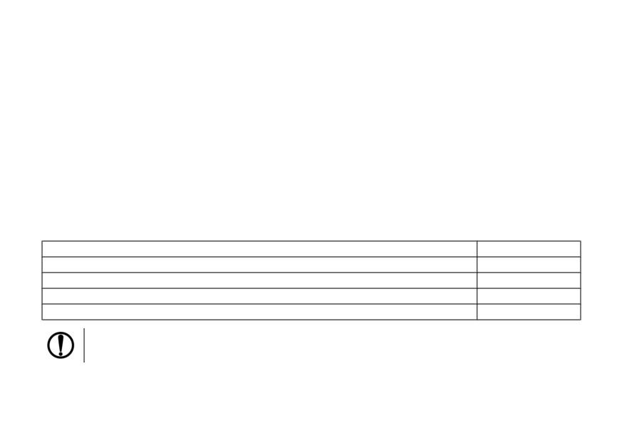
12 Scope of delivery
Description
Quantity
Device
1 pc.
Passport and warranty card
1 pc.
User manual
1 pc.
Mounting kit
1 kit
NOTICE
The manufacturer reserves the right to make additions to the slope of delivery.
54
13 Warranty
The manufacturer guarantees conformity of the Device to requirements of technical conditions (ТУ)
under the conditions of operation, transportation, storage and installation.
Warranty period of operation: 24 months from the date of sale.
In case of failure of the Device during the warranty period at observance of conditions of operation,
transportation, storage and installation the manufacturer undertakes to provide free repair or
replacement.
The procedure for transferring the Device to repair is described in the passport and in the warranty card.
55
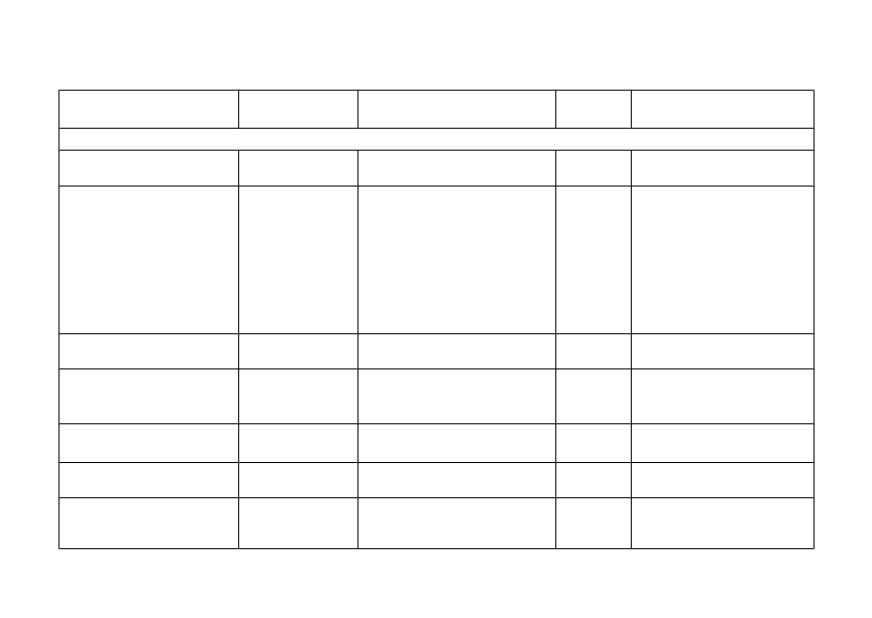
Appendix A. Device parameters
Modbus
Parameter
Allowed values
Data type
Notes
register, HEX
Network parameters
Protocol
0 - ASCII;
unsigned
Write / Read
0x0008
S..PRO
1 - RTU
char
Default - 1
0 - 2400;
1 - 4800;
2 - 9600;
3 - 14400;
Baud rate, bps
unsigned
Write / Read
0x0009
4 - 19200;
bPS
char
Default - 8
5 - 28800;
6 - 38400;
7 - 57600;
8 - 115200
Data word length, bits
unsigned
Read
0x000A
1-8
LEN
char
Default - 1
0 - no control (NONE);
Parity
unsigned
Write / Read
0x000C
1- parity (EVEN);
PRTY
char
Default - 0
2 - parity (ODD)
Stop bits
0 - 1 stop bit (1);
unsigned
Write / Read
0x000B
Sbit
1 - 2 stop bits (2)
char
Default - 0
Device address
unsigned
Write / Read
0x0006
from 1 to 247
Addr
short
Default - 16
Write / Read
Response delay, ms
unsigned
0x000D
from 0 to 45
Default - 2
rS..dL
char
56
Modbus
Parameter
Allowed values
Data type
Notes
register, HEX
Parameters for devices with analog output
0 - output is off (0)
Analog output mode
1 - directly proportional (1);
unsigned
Write / Read
0x0031
OUTDAC
2 - inversely proportional (2);
char
Default - 3
3 - recorder (3)
Write / Read
Setting value U of the
0x0032
Unsigned
Only for directly
analog output
from 0 to FREQ
0х0033
long
proportional mode.
udAc
Default - 0
Write / Read
Value of the direct
0x0034
Unsigned
Only for directly
proportionality zone
from 1 to FREQ
0х0035
long
proportional mode.
dPro
Default - 1
Value of the lower
Write / Read
0x0036
Unsigned
registration limit (U-L)
from 0 to FREQ
Only in the recorder mode.
0х0037
long
LOR
Default - 0
Upper registration limit
Write / Read
0x0038
Unsigned
value (U-H)
from 0 to FREQ
Only in the recorder mode.
0x0039
long
Hir
Default - 2500
0 - the value LdAC(0) is
Analog output status when
Write / Read
output;
unsigned
control is disabled
0x003A
Default - 0
1 - the value HdAC(1) is
char
OFFdAC
output
57
Modbus
Parameter
Allowed values
Data type
Notes
register, HEX
Parameters for devices with digital output
0 - tachometer measurement
Signal source for digital
result (tACHo);
unsigned
Write / Read
output
0x0013
1 - the value HdAC(LiFE.t) is
char
Default - 0
SrCC
output
0 - output control is disabled
(the output is transferred to
the state defined by the
parameter oFFdo) (0);
Write / Read
1 - logic type 1 (reverse
Only for input of the
Logic type of digital output
hysteresis) (1);
unsigned
0x0014
comparator - tachometer
OUTDO
2 - logic type 2 (direct
char
(SrCC = tACHo)
hysteresis) (2);
Default - 0
3 - logic type 3
(direct proportional) (3);
4 - logic type 4
(reverse proportional) (4);
Write / Read
Default - 0.
Digital output trigger
0 - disabled (oFF);
unsigned
When setting the
0x0015
dobLK
1 - enabled (on)
char
parameter to state on, the
digital output retains its last
state
Digital output delay, s
unsigned
Write / Read
0x0016
from 0 to 999
dodELA
short
Default - 0
Setpoint for digital output
Write / Read
0x0017
Unsigned
control
from 0 to FREQ
Default - 10
0х0018
long
UdO
at OUTDO > 0
58

Modbus
Parameter
Allowed values
Data type
Notes
register, HEX
Write / Read
Default - 1
at OUTDO > 0.
0x0019
Unsigned
The hysteresis in
Comparator hysteresis DU
from 0 to FREQ
0х0020
long
combination with the
setpoint must not go
beyond the set limits of the
device registration
Setting value for digital
Write / Read
output run hours control,
unsigned
0x001B
from 0 to 9999
At SrCC = LiFE_t.
days
short
Default - 0
UdAY
Setpoint value for
Write / Read
controlling the digital
unsigned
0x001C
from 0 to 23
At SrCC = LiFE_t.
output on running hours, h
char
Default - 0
UHOUR
Setpoint value for control
Write / Read
of digital output on running
unsigned
0x001D
from 0 to 59
At SrCC = LiFE_t.
hours, min
char
Default - 0
UMIN
Setpoint value for control
Write / Read
of digital output on running
unsigned
0x001E
from 0 to 59
At SrCC = LiFE_t.
hours, s
char
Default - 0
USec
Digital output status when
Write / Read
control is disabled
0 - output is off (oFF)
unsigned
0x001F
At OUTDO = 0.
(OUTDO = 0)
1 - output is on (on)
char
Default - 0
OFFDO
59
Modbus
Parameter
Allowed values
Data type
Notes
register, HEX
0 - rps (SEC);
Tachometer reading
1 - rpm (Min)
unsigned
Write / Read
0x0020
DTTA
2 - rph (HOUR);
char
Default - 0
3 - adjustable values (User)
Write / Read
Buffer filling time of 8
Tachometer reading filter
unsigned
0x0021
from 0 to 50 s
values for averaging
MAV..L
char
readings.
Default - 1
0 - _ _ _ _ _ _;
Decimal point position of
1 - _ _ _ _ _._;
unsigned
Write / Read
device readings
0x0022
2 - _ _ _ _._ _;
char
Default - 0
dP
3 - _ _ _._ _ _;
4 - _ _._ _ _ _
0 - _ _ _ _ _ _;
Multiplier decimal point
1 - _ _ _ _ _._;
unsigned
Write / Read
position
0x0023
2 - _ _ _ _._ _;
char
Default - 0
FDP
3 - _ _ _._ _ _;
4 - _ _._ _ _ _
from 1 to 999
Multiplier
unsigned
Write / Read
0x0024
(from 0.0001 to 999 including
F
short
Default - 1
FDP)
Maximum frequency of the
input signal at the counting
0x0025
Unsigned
Write / Read
from 1 to 2500
input, Hz
0х0026
long
Default - 2500
FREQ
60
Modbus
Parameter
Allowed values
Data type
Notes
register, HEX
Minimum pulse duration,
0х0040
Unsigned
Write / Read
µs
from 10 to 999999
0х0041
long
Default - 10
minImp
Password
0x0027
Unsigned
Write / Read
from 0 to 999999
PASS
0х0028
long
Default - 0
The measured value of
rounds in units
corresponding to the value
0x0029
Unsigned
from 0 to 4294967296
Read only
DTTA.
0х002A
long
Not displayed on the
digital indicator
Running hours, s
0х002B
Unsigned
Not displayed on the
from 0 to 863999999
Read only
0х002C
long
digital indicator
State of digital output 1
0 - output is off (oFF)
unsigned
0x002D
Read only
OST
1 - output is on (on)
char
State of digital output 2
0 - low level (0);
unsigned
0x002E
Read only
iSt
1 - high level (1)
char
0x0000
Device name
0x0001
__ТH01
char[6]
Read only
DEV
0x0002
0x0003
Firmware version
Read only
0x0004
_VХ.ХХ
char[6]
VER
0x0005
61
Modbus
Parameter
Allowed values
Data type
Notes
register, HEX
0 - no output;
Version of the device.
1 - only digital output;
unsigned
Not displayed on the
0x0012
Read only
2 - only analog output;
char
digital indicator
3 - digital and analog outputs
Commands
Reset running hours
unsigned
0x002F
1 - reset counter (YES)
Write only
counter rES..t
char
Restore factory settings
1 - restore factory settings (
unsigned
0x0030
Write only
dEFAUL
YES)
char
Write only
Apply network settings
unsigned
New parameters take
0x000F
1 - apply settings (YES)
APPLY
char
effect after command
APPLY or reboot
Calibration
The value of the code
Read
issued by the DAC to set
unsigned
0x003B
from 0 to 1023
Only in calibration mode
the minimum value of the
short
Default - 40
output signal
The value of the code
Read
issued by the DAC to set
unsigned
0x003C
from 0 to 1023
Only in calibration mode
the maximum value of the
short
Default - 1023
output signal
Write only
Displacement of the lower
The desired offset of the
signed
limit of the current output
0x003D
from -1000 to 1000
DAC code relative to the
short
LdAC
current is transmitted.
Default - 0
62
Modbus
Parameter
Allowed values
Data type
Notes
register, HEX
Write only
Displacement of the upper
The desired offset of the
signed
limit of the current output.
0x003E
from 1000 to -1000
DAC code relative to the
short
HdAC
current is transmitted.
Default - 0
Apply current output
0 - do not apply;
unsigned
Write only
calibration
0x003F
1 - apply
char
Default - 0
APPLY
63
Appendix B. Possible malfunctions and solutions
Manifestation
Possible cause
Method of elimination
On the digital indicator in an operating
The whole part of the measured value
Set a different display scale (rps, rpm,
mode it is displayed:
does not fit on the digital display
rph or custom mode)
------
The digital indicator in the setup mode
Set the parameter value taking into
displays:
Value does not fit on digital indicator
account the size of the digital
НННННН
indicator (6 characters)
64