СИ30 Pulse counter. User manual
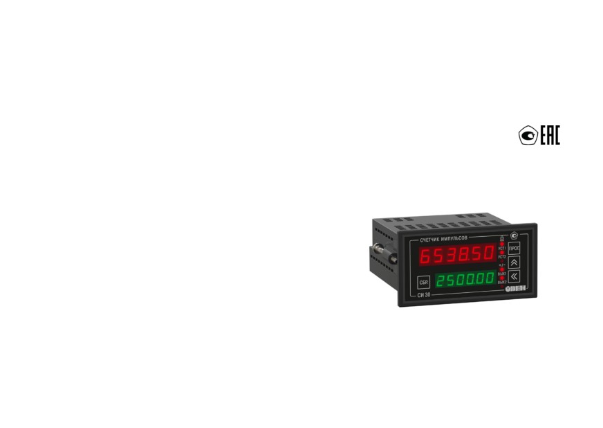
СИ30
Pulse counter
User manual
Contents
Safety instructions
4
Introduction
5
1 Purpose and functions
7
2 Specifications and operating conditions
7
2.1 Specifications
7
2.2 Operating conditions
9
3 Safety measures
10
4 Mounting
11
4.1 Installation of device in housing Н
11
4.2 Installation of device in housing Щ1
13
4.3 Installation of device in housing Щ2
16
5 Electrical connections
18
5.1 Wiring recommendations
18
5.2 Getting Started
19
5.3 Pin assignment
20
5.4 Connection of switching devices and sensors
21
5.5 Connecting load to the outputs
26
6 Operation of the device
29
6.1 Principle of operation
29
6.2 Control and indication
31
6.3 Switch on and operation
35
7 Setup
36
7.1 Sequence of setup
36
2
7.2 Setting the operating mode of the counter
42
7.3 Configuring the device from PC
53
8 Maintenance
53
9 Marking
53
10 Packaging
54
11 Transportation and storage
54
12 Scope of delivery
55
13 Warranty
55
Appendix A Device parameters
57
3
Safety instructions
Following symbols and keywords are used in this manual:
DANGER
Keyword DANGER is used to warn about an imminent threat to health. Possible
consequences may include death, permanent or prolonged incapacity for work.
WARNING
Keyword WARNING is used to warn about damage to property and devices. Possible
consequences may include damage to property, for example, this device or connected
devices.
CAUTION
Keyword CAUTION is used to prevent a potentially dangerous situation. Possible
consequences may include minor injuries.
NOTICE
Keyword NOTICE is used for supplement, clarifying, interpretation of the main text and/or
clarifying specific aspects of working the device operation.
4
Introduction
This user manual is intended to familiarize service personnel with the design, principle of operation,
structure, operation and maintenance of the pulse counter СИ30 (further in the text called «device»).
Connection, setup and maintenance should be made only by qualified specialists after reading this
manual.
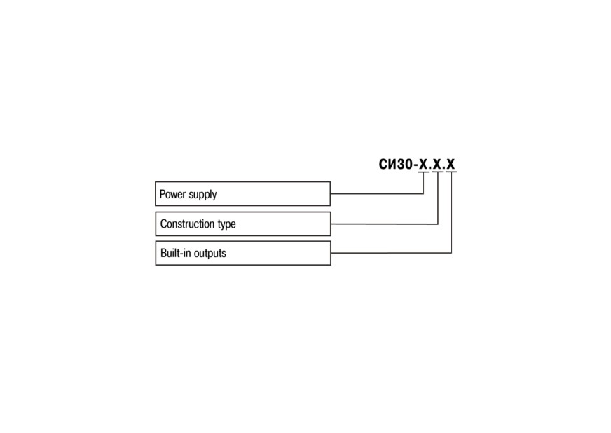
The device is produced in various modifications, that are encrypted in code of full conventional
designation.
Power supply:
220 - 90...250 V AC, 50 Hz;
24 - 10,5...30 V DC.
Construction type:
Н - wall-mounting housing;
Щ1 - panel-mounting housing (square front panel, 96x96 mm);
Щ2 - panel-mounting housing (rectangular front panel, 96x48 mm).
5
Built-in outputs:
Р - electromagnetic relay;
К - transistor optocoupler of n-p-n type;
С - triac optocoupler.
The example of designation used for ordering and in other products documentation:
Pulse counter СИ30-220.Щ2.Р ТУ 4278-007-46526536-2010.
6
1 Purpose and functions
The device is a universal counter that can be used for a wide range of automation tasks. It is designed
to count the number of pulses coming to its inputs in direct and opposite direction and to convert further
this number into a physical value (using multiplication by given multiplier).
The device can perform following functions:
• count-up, count-down, reversing and other types of counting pulses from the connected sensors;
• determination of the direction of rotational motion of units and mechanisms;
• converting the number of pulses into real units of measurement;
• powering sensors from the built-in 24 V DC power source;
• load control by two built-in outputs;
• saving counting results when power is turned off;
• connection to PC via embedded RS-485 and USB interfaces.
2 Specifications and operating conditions
2.1 Specifications
Main specification of the device is given in Table 2.1.
Table 2.1 - Device features
Item
Value
Power supply
AC:
• supply voltage
90...250 V
(nominal - 110, 220 or 240 V)
• frequency
47...63 Hz (nominal - 50 and 60 Hz)
7
Table 2.1 (continued)
Item
Value
DC
10.5...30 V
Power consumption, max.
12.5 VA
Inputs
Number of control inputs
4
Logical 0
0...4 V
Logical 1
10...30 V
Current for sensor’s polling
2 mA
Nominal supply voltage of the sensors
24 V
Instability of sensor supply voltage
10 %
Load current for power supply of sensors, max.
100 mA
Outputs
Number of outputs
2
Current switched by relay contacts, max.
8 A (220 VAC, cos φ > 0.4)
Current of transistor optocoupler load, max.
0.2 A (at 50 V)
Current of optotriac load, max.:
- at 240 V (constantly open triac)
50 mA
- if the triac is switched on with frequency = 50 Hz max
0.5 A
and timp = 5 ms
Pulse counter
Number of display digits
6
Counting speed, max.
10 000 Hz
Duration of input pulses, min.
50 µs
8
Table 2.1 (continued)
Item
Value
Range of values of the multiplier
from 0.00001 to 99999
Frequency of input filter
from 1 to 50000 Hz
Pulse ratio, min.
2
Limit of permissible basic error (according to GOST
±1 junior digit
24907)
Basic reduced error for measurement of time intervals
±1% from 0.1 to 999.99 сtr
Housing
Dimensions:
• wall-mounting Н
105х130х65 mm
• panel-mounting Щ1
96х96х70 mm
• panel-mounting Щ2
96х48х100 mm
Protection class:
• wall-mounting Н
IP44
• panel-mounting Щ1 and Щ2
IP54 (front panel side)
Device features
Weight, max.
1 kg
Average service life
8 years
Calibration interval
2 years
2.2 Operating conditions
The device must be used in following conditions:
• closed explosion-proof areas without aggressive vapors and gases;
9

• ambient temperature from -20 to +70 °С;
• upper limit of relative humidity = max. 95% at 35°C and lower temperatures without moisture
condensation;
• atmospheric pressure from 84 to 106.7 kPa.
In terms of resistance to mechanical influences during operation the device corresponds to group of
performance N2 in GOST R 52931-2008.
NOTICE
It is necessary to comply with the requirements for operating conditions, as they are part of
safety measures.
3
Safety measures
CAUTION
The terminal block has life-threatening voltage up to 250 V. Any connections to the device and
maintenance work should be carried out only when the power is turned off.
By the method of protection from electric shock the device corresponds to class II according to GOST
12.2.007.0-75.
While operating, maintaining and checking, it is necessary to comply with GOST 12.3.019-80, Rules of
the technical operation of electrical consumers and Safety rules for operating electrical equipment.
There must be no moisture on the output terminals and the internal components of the device. It is
forbidden to use the device in corrosive environments with acids, alkalis, oils , etc. in the air.
10
4 Mounting
4.1 Installation of device in housing Н
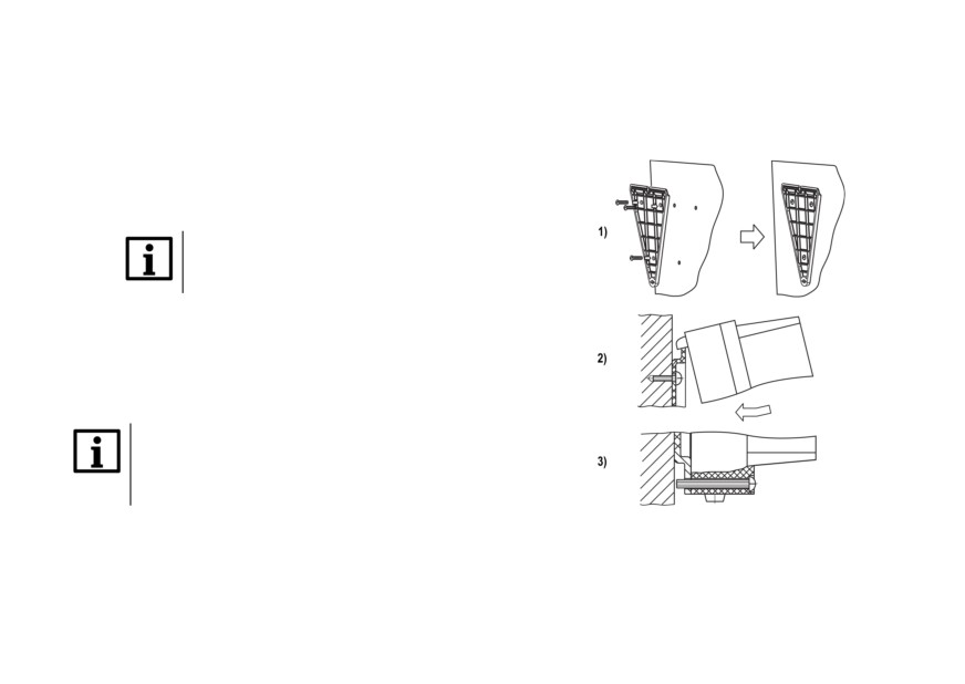
For installation of the device perform following actions:
1. Fasten the bracket on the surface intended for
mounting with three M4 × 20 screws (see
Figure 4.2).
NOTICE
Screws for bracket are not included in the
package.
2. Hook the fixing bracket from the back panel of
device to the upper edge of the wall bracket.
3. Attach device to the bracket with the supplied
screw.
Demount the device in the reverse order.
NOTICE
Remove the cover before wiring. Fasten the
base of the device to the bracket with a
supplied screw.
Figure 4.1 - Installation of wall-mounting
device
11
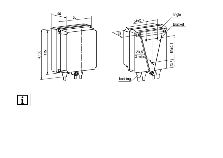
Figure 4.2 - Dimensions of H housing
NOTICE
The bushings need to be cut in accordance with the diameter of the lead-in cable.
12
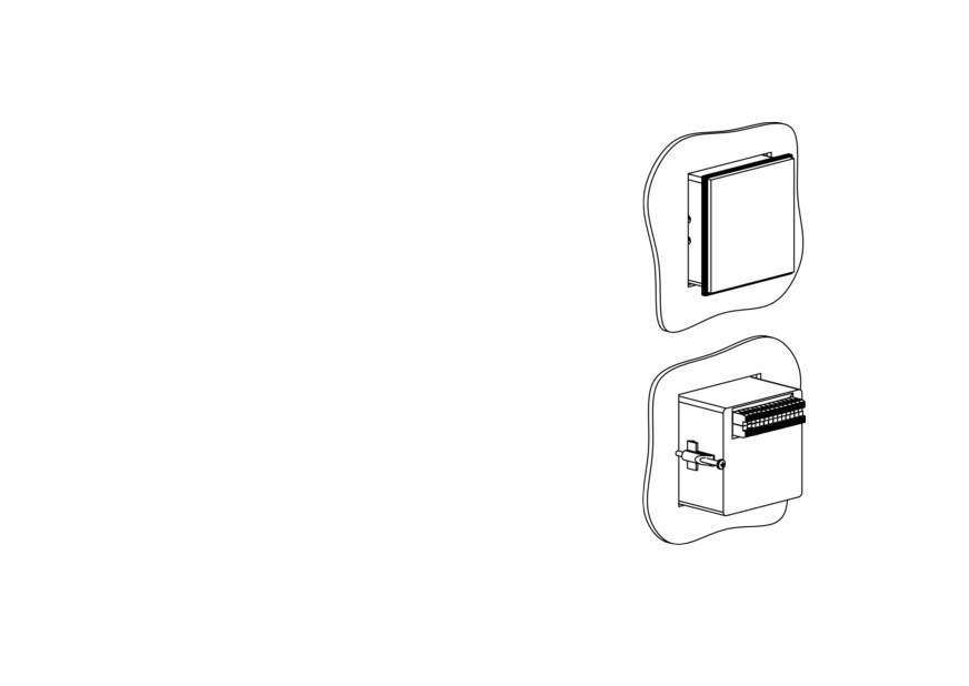
4.2 Installation of device in housing Щ1
For installation of the device perform following actions:
1. Prepare a place for mounting on the control panel
(see Figure 4.4).
2. Install the gasket on the frame of the device to
ensure degree of protection IP54.
3. Insert the device into a specially prepared hole on
the front of the control panel.
4. Insert the supplied retainers into holes on the
sides of the device.
5. Tighten supplied screws M4 x 35 in the holes of
each retainer so that the device is pressed firmly
to the front of the control panel.
Demount the device in the reverse order.
Figure 4.3 - Installation of panel-
mounting device
13
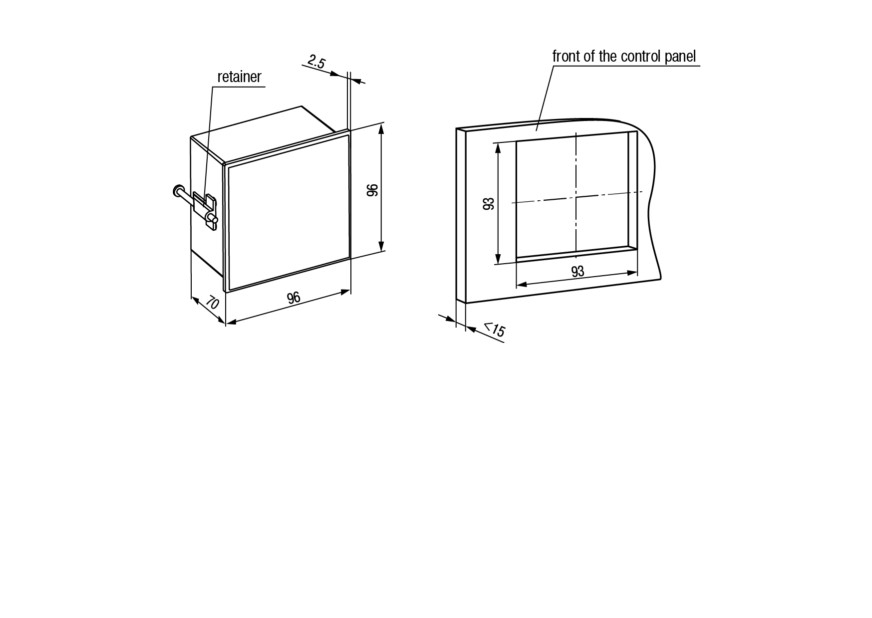
Figure 4.4 - Dimensions of Щ1 housing
14
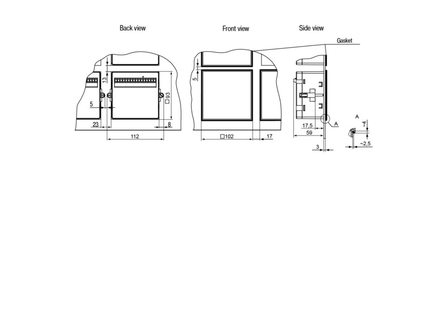
Figure 4.5 - Device in Щ1 housing mounted in the control panel with 3 mm thickness
15
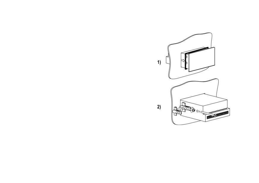
4.3 Installation of device in housing Щ2
For installation of the device perform following actions:
1. Prepare a place for mounting on the control panel
(see Figure 4.8).
2. Install the gasket on the frame of the device to
ensure degree of protection IP54.
3. Insert the device into a specially prepared hole on
the front of the control panel.
4. Insert the supplied retainers into holes on the
sides of the device.
5. Tighten supplied screws M4 x 35 in the holes of
each retainer so that the device is pressed firmly
to the front of the control panel.
Disassemble the device in the reverse order.
Figure 4.6 - Installation of panel-
mounting device
16
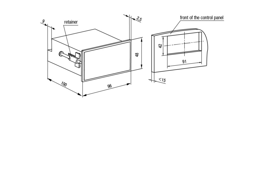
Figure 4.7 - Dimensions of Щ2 housing
17

Figure 4.8 - Device in Щ2 housing mounted in the control panel with 3 mm thickness
5 Electrical connections
5.1 Wiring recommendations
To ensure the reliability of electrical connections it is recommended to use copper multicore cables, the
ends of which should be carefully cleaned, tinned, otherwise use cable lugs before connection.
Stripping of conductors must be performed in such way that the stripped ends after connecting to the
device do not protrude beyond the terminal block. Cable cross section should be no more than 1 mm2.
General requirements for connection lines:
• During the cabling, communication lines that connect the device with sensors must be isolated to
a separate circuit (or several circuits) and placed separately from power cables or other sources
of high-frequency and impulse interferences.
18
• To protect the device inputs from the effects of industrial electromagnetic interference, the
communication lines between device and sensors should be screened. Special cables with
shielding or grounded steel pipes of suitable diameter can be used as screens. The cable
shielding should be connected to the functional ground terminal (FE) in the control panel.
• Network interference filters should be installed in the power supply lines.
• It is necessary to install spark-suppression filters in the lines of switching of power equipment.
When mounting the system in which the device is used, the rules for effective grounding should be
taken into account:
• all grounding lines must be laid in Y-connected circuit, ensuring good contact with the grounding
element;
• all earthing circuits must be made with wires of the largest possible cross-section;
• it is forbidden to connect the device terminal "Common" with grounding lines.
5.2 Getting Started
DANGER
After unpacking the device, make sure that it has not been damaged during transportation.
If the device has been for a long time at a temperature below minus 20 °C, it is necessary to keep it in a
room with a temperature corresponding to the operating range for at least 30 minutes before switching
on and operation.
For connecting the device perform following actions:
1. Connect the device to a power source.
19
CAUTION
Before powering up the device, it is necessary to check the correct connection of the
supply voltage and its level.
2. Connect the "device - sensors" communication lines to the sensors and to device inputs.
3. Connect the "device - load" communication lines to the actuators and to outputs of the device.
4. Apply power to the device.
5. Set up the device.
6. Power off the device.
5.3 Pin assignment
Screw terminals are located on the back wall of the panel-mounting device or inside the device (wall-
mounting). The terminal block contacts assignment is shown in Figure 5.1.
20
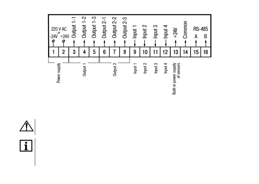
Figure 5.1 - Terminal block contacts assignments
5.4 Connection of switching devices and sensors
CAUTION
Supply voltage on the device inputs (pins 9 - 12 at the terminal block) must be in range from 0
to 24 V.
NOTICE
To supply the switching devices and sensors to the screw terminal block of the device is
provided with supply voltage (pin 13 of the terminal block). If power consumption of input
exceeds the load capacity of the built-in power supply (24 V), then an external power supply
with an output voltage of 12 to 34 V (24 V recommended) must be used for powering.
21
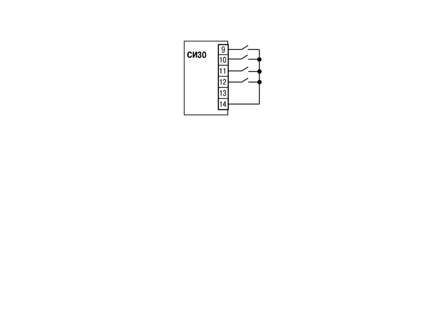
Scheme for connection of the switching devices to the inputs is shown in Figures 5.2 and 5.3 .
Figure 5.2 - Connection of "dry contact" switching devices
22
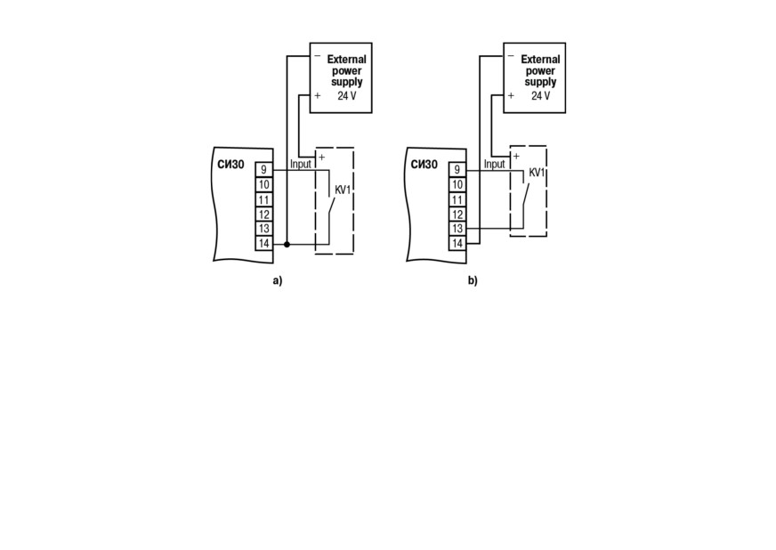
Figure 5.3 - Connection of switching devices: a) for operation with n-p-n sensors; b) for
operation with p-n-p sensors
Scheme for connection of passive and active sensors with an output n-p-n open-collector transistor or
p-n-p is shown in Figures 5.4 and 5.5 accordingly.
23
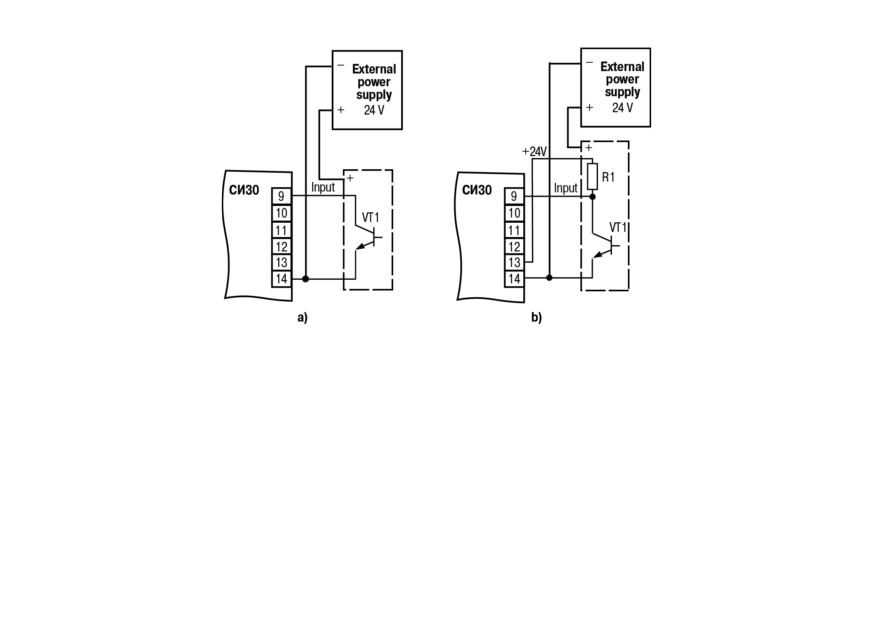
Figure 5.4 - Connection of n-p-n-sensors: a) active; b) passive
24
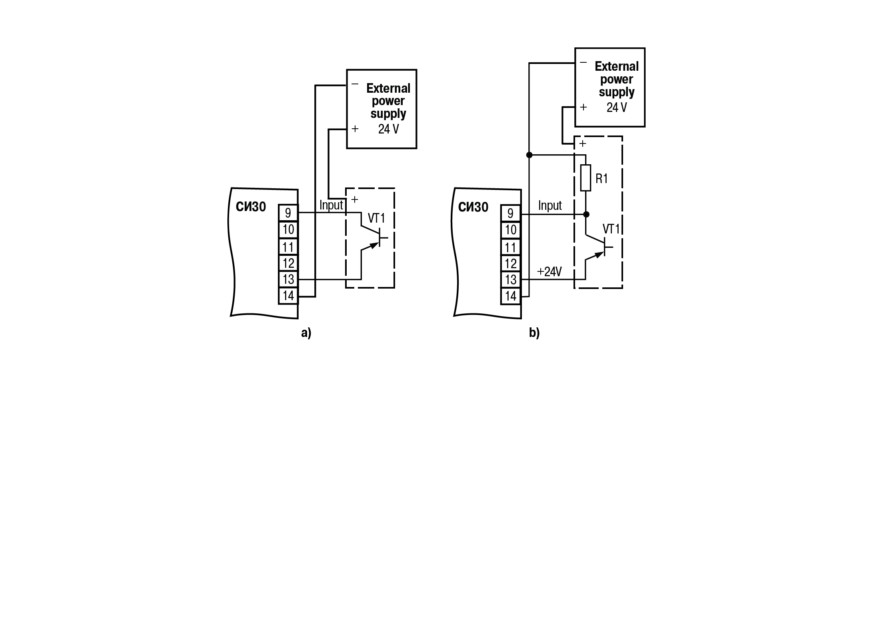
Figure 5.5 - Connection of p-n-p-sensors: a) active; b) passive
Device has a dual switch for selecting, which of the types of sensors will work. It is located on the lateral
side of the housing Щ1 and Щ2. For device in the H housing, the switch is located inside the housing (to
access the switch, it is necessary to remove the device cover by unscrewing the four screws that fasten
the cover to the base). Appearance of the switch is shown in Figure 5.6.
25
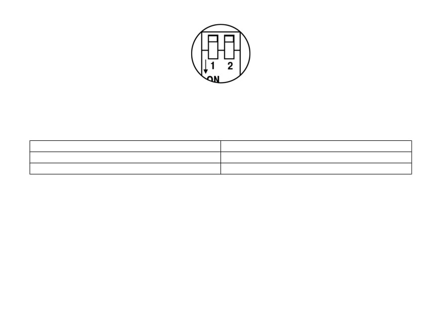
Figure 5.6 - Dual switch
Positions of the switch depending on which device operates with different sensors, are shown in
Table 5.1.
Table 5.1 - Switch status for different types of sensors
Type of sensors
Switch positions
n-p-n
1 - OFF↑; 2 - ON↓
p-n-p
1 - ON↓; 2 - OFF↑
5.5 Connecting load to the outputs
Outputs can be made in the form of electromagnetic relays (P), transistor (K) or triac (C) optocouplers.
The outputs are used for direct load control (on/off) or for control by more powerful elements:
contactors, solid state relays, thyristors or triacs. The outputs are galvanically isolated from the circuit of
the device.
Scheme of connecting the load to the electromagnetic relay is shown in Figure 5.7.
26
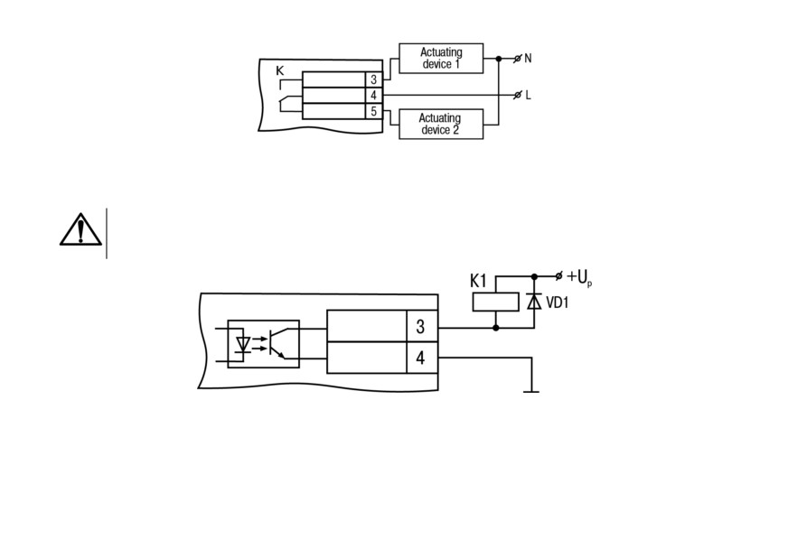
Figure 5.7 - Scheme of connecting load to the output of type Р
A transistor optocoupler is usually used to control a low-voltage relay (up to 50 V) - see Figure 5.8.
CAUTION
The diode VD1 (KD103 or similar type) should be installed in parallel to the relay coil, in order
to avoid failure of the transistor due to the large self-induction current.
Figure 5.8 - Scheme of connecting load to the output of type К
The optosimistor is connected to the control circuit of the power triac through the limiting resistor R1
according to the scheme shown in Figure 5.9.
27
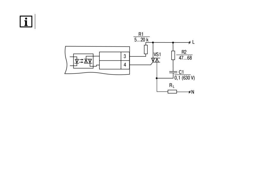
NOTICE
Nominal value of the resistor determines the current of the triac.
Figure 5.9 - Scheme of connecting a power triac to the output of type C
Optosimistor can also control a pair of anti-parallel connected thyristors (see Figure 5.10).
28
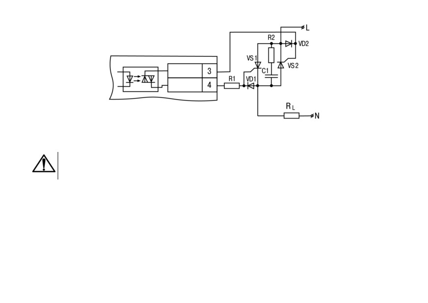
Figure 5.10 - Scheme of connecting two anti-parallel connected thyristors
to the output of type С
CAUTION
It is recommended to connect a filtering circuit (RC) to the terminals of thyristors or triacs in
order to prevent breakdown due to high-voltage power surges in the network.
6 Operation of the device
6.1 Principle of operation
Functional diagram of the device is shown in Figure 6.1.
29
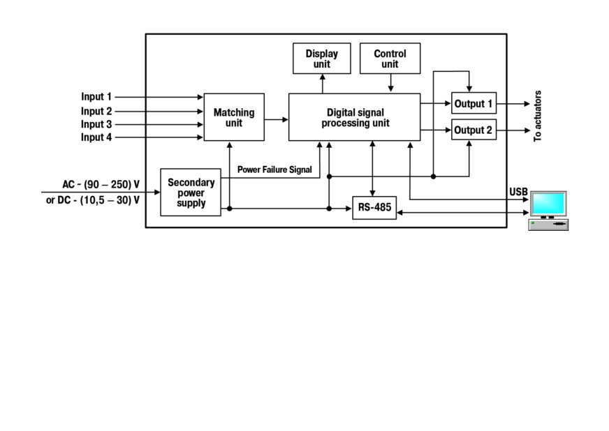
Figure 6.1 - Functional diagram
The device has four independent digital inputs for external control signals. To the inputs can be
connected:
• switching devices (buttons, switches, reed switches, relays, etc.);
• sensors with output n-p-n-transistor with an open collector;
• sensors with output p-n-p-transistor.
The levels of the input signals are converted and processed in the matching unit and then sent to the
digital signal processing unit that performs:
• reassignment of inputs in accordance with the selected counting mode (see section 7.2);
30
• filtering of input signals (see section 6.3);
• counting incoming pulses on the device inputs;
• convertion of the value from the counter into real physical value;
• comparing signal value to the setpoint before displaying;
• generation of signals for controlling the outputs according to a specified algorithm.
Control unit includes buttons for entering parameters of the device.
Display unit displays the measurement results or operating parameters on the indicators and shows
the counter status using LEDs.
Secondary power supply converts the incoming voltage for all units of the device, depending on the
version (with AC or DC power supply), and generates a signal indicating the loss of supply voltage.
The device can be connected with PC using RS-485 and USB interfaces that allow to set and edit the
device configuration, monitor its current status and indications.
6.2 Control and indication
Elements of indication and control are located on the front panel of the device (see Figures 6.2 and 6.3):
• two seven-segment six-digit digital indicators, red and green - see Table 6.1;
• six/eight LEDs (depending on the construction type) - see Table 6.2;
• four/five buttons (depending on the construction type) - see Table 6.3.
All elements are placed on two (in housings Щ1 and Н) or on three printed circuit boards (in housing
Щ2).
31
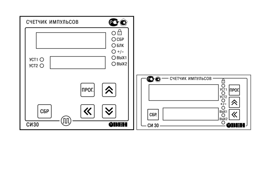
Figure 6.2 - Front panel of the device in housings for Figure 6.3 - Front panel of the device in housing for
wall-mounting H and panel-mounting Щ1
panel-mounting Щ2
32
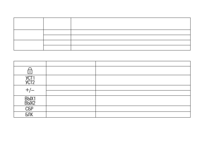
Table 6.1 - Assignment of digital indicators
Operating
Indicator
mode of the
Displayed information
device
Upper indicator
Operation
Current counter value
(red)
Setup
Name of the selected parameter
Lower indicator
Operation
Setpoint value
(green)
Setup
Parameter value
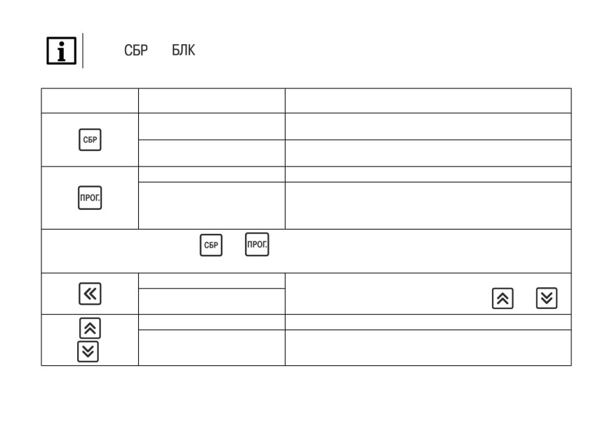
Table 6.2 - LEDs assignment
LED
Status
Description
lights
Key lock is on
Number of setpoint (1 or 2) that is currently displayed on the
lights
lower indicator
lights
Direct counting
extinguished (off)
Reverse counting
lights
Сurrently enabled output
lights
Input Reset is enabled
lights
Input Lock is enabled
*
33
NOTICE
* LEDs
and
are not available on the housing Щ2.
Table 6.3 - Buttons assignment
Operating mode of the
Button
Functions
device
Resetting (similar to incoming "Reset" signal on the device
Operation
input)
Return previous (non-changed) value of the parameter during
Setup
editing
Operation
Change the values of setpoints
• Enter and exit the settings group
• Enter the parameter editing mode and exit
Setup
• Save the new parameter value in non-volatile memory
of the device
Pressing at the same time buttons
and
and holding them for 2 sec opens access to configuration setup
(PC-interface parameters).
Operation
Select the digit to edit when changing the parameter value or
Setup
entering the password (used with the buttons
and
)
Operation
Change the values of setpoints
View parameter values and edit them,
Setup
enter a password
*
34

NOTICE
* The button
is not available on the housing Щ2.
6.3 Switch on and operation
During operation, the device counts the number of incoming pulses at its counting input, compares it
with setpoint, converts this quantity into a physical value, and displays the value on the indicator. Device
can operate in following modes of counting:
• count-up;
• count-down;
• command;
• individual;
• reversing;
• quadrature.
During operation the counter interprets different types of signals. On the device input first incoming
pulse is considered as Start signal for counting. Counting stops when the Stop signal (next pulse)
comes.
If there is an active "Reset" signal, the number of counted pulses is reset (counting continues from 0).
Block prevents the transmission of the counting pulses to the device input. While this signal is active,
counting is blocked.
35

CAUTION
The setpoint is specified with the same accuracy as for counting physical values.. The
multiplier can be set from 0.00001 to 99999. The conversion of counting results (result of
multiplying) will be rounded up.
Read more about each of the counting modes, see section 7.2.
The counter also filters the input signals with two filters. The first one filters the signal on the counting
input by pulse duration (from 1 to 50,000 Hz), the second filters signal on the control inputs of the
device (from 1 to 999999 microseconds).
7 Setup
7.1 Sequence of setup
The Setup mode is intended for viewing and editing the device parameters. New parameters are saved
to non-volatile memory of the device.
To enter (or exit) the Setup mode, press and hold button
for at least 2 seconds. For access to
configuration setup (parameters of connection with PC) press at the same time buttons
and
and hold them for 2 sec.
While editing, if no button is pressed within 2 min., device automatically restores previous value of the
parameter and returns to parameter view mode. If within 3 minutes there are no actions in Setup menu,
device automatically returns to Operation.
36
When device enters Setup for the first time, upper indicator shows PASS. Enter a new 4-digit password
(default is 0000), save it and memorise. This password is further required for changing the device
settings and for restoring factory settings (dEFAUL).
NOTICE
If you forgot your password, Setup mode can be entered with password 1098. When this value
is entered, password is reset to 0000. Therefore, it is not recommended to set the new user
password as 1098, because in this case, each time the password is entered, its value will be
reset to default.
Structure of the device settings menu and sequence of pressing the buttons for setup is shown in
figure 7.1 and figure 7.2.
37
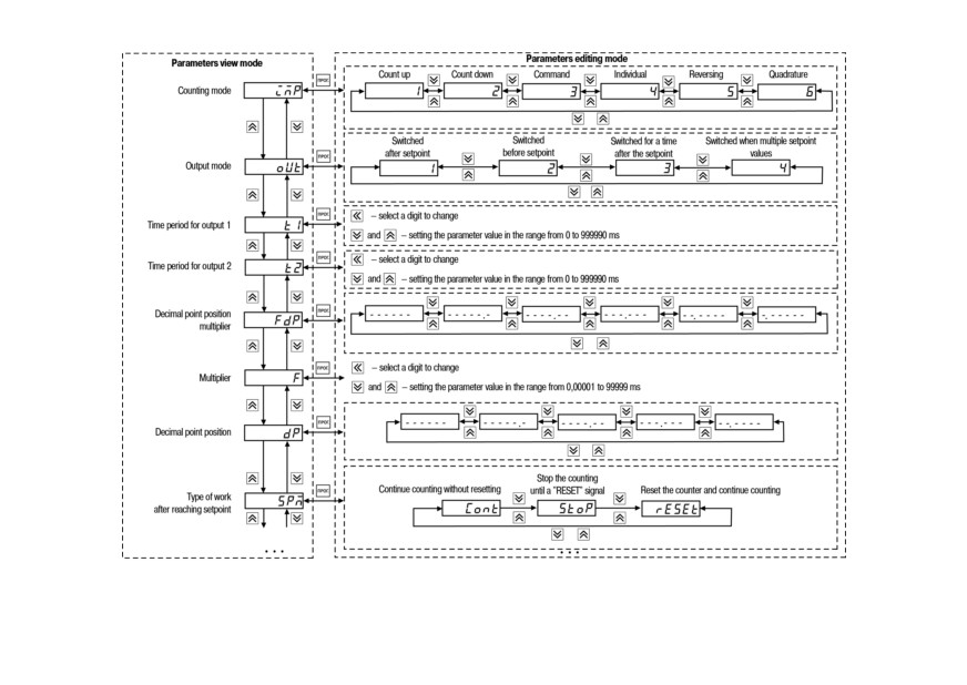
Figure 7.1 - Device settings menu (beginning)
38
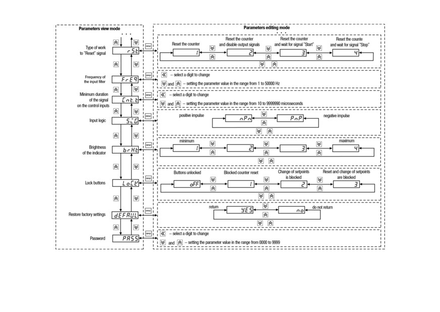
Figure 7.2 - Device settings menu (ending)
39
Since the FDP and DP parameters set restrictions on each other (the number of displayed digits after the
decimal point in the counting results can not be larger than the number of digits after the decimal point
of the entered multiplier), editing of parameters FDP, DP, F should be performed in the following
sequence:
• to increase the number of displayed digits after the decimal point (decimal point offset to the left):
◦ set parameter FDP;
◦ set parameter F;
◦ set parameter DP;
• to decrease the number of displayed digits after the decimal point (decimal point offset to the
right):
◦ set parameter DP;
◦ set parameter FDP;
◦ set parameter F.
Structure of the RS-485 configuration settings menu and sequence of pressing the buttons for setup
is shown in Figure 7.3.
NOTICE
The list of configurable parameters of the device and their possible values is shown in
Appendix A.
40
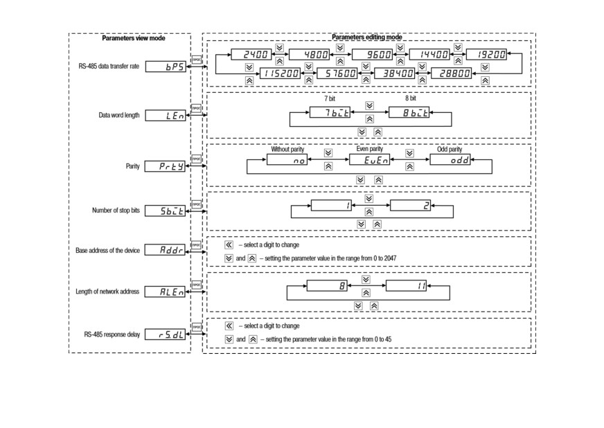
Figure 7.3 - RS-485 settings menu RS-485
41
7.2 Setting the operating mode of the counter
Availiable types of counting (depending on the values of parameter inP) are presented in Table 7.1.
42
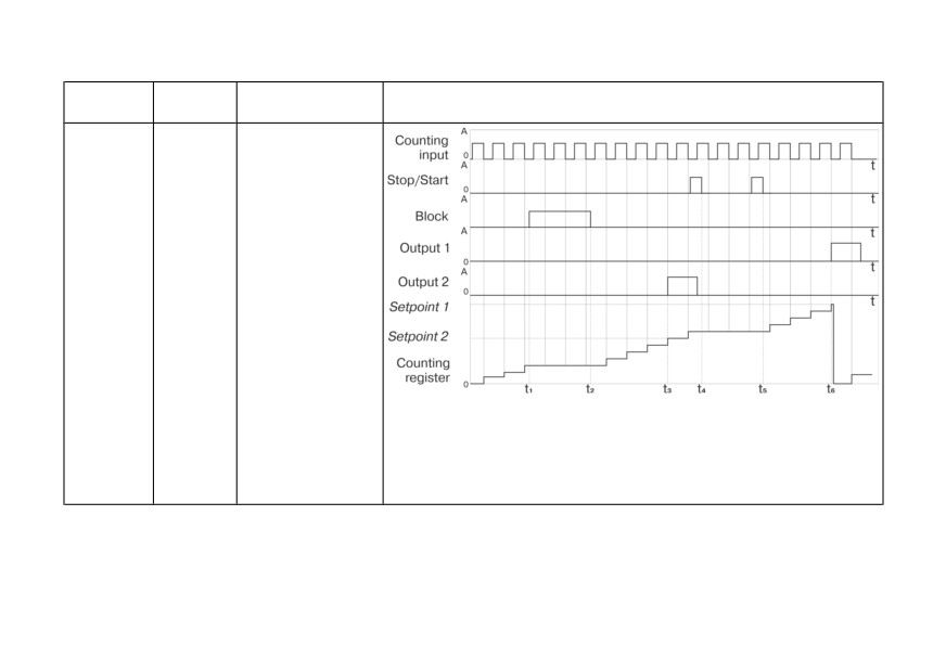
Table 7.1 - Types of counting
Name of
Input
Principle of
Illustration
the mode
functions
operation
Count-up
Input 1 -
Counting pulses
(inP = 1)
count
from zero upwards.
Input 2 -
When the highest
start/stop
setpoint is reached,
Input 3 -
the corresponding
reset
output is switched
Input 4 -
and the counter is
block
reset
{t1-t2} - blocking signal the counting inputs;
t3 - moment of switching of output 2 in case of coincidence of values of
the counting register and setpoint 2;
{t4-t5} - stop-start signal;
t6 - moment of switching of output 1 in case of coincidence of values of
the counting register and setpoint 1
43
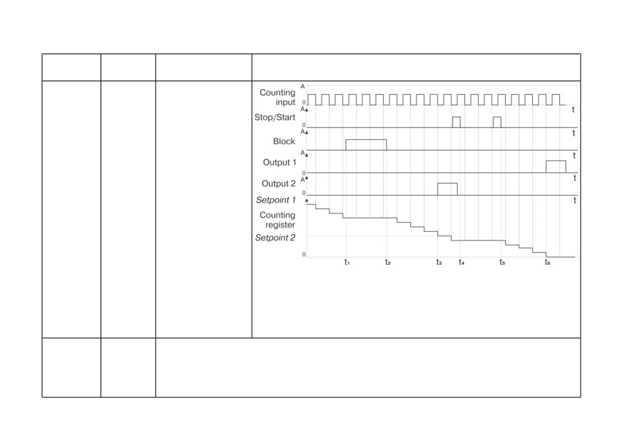
Table 7.1 (continued)
Name of
Input
Principle of
Illustration
the mode
functions
operation
Count-
Input 1 -
Counting pulses
down
count
from the highest by
(inP = 2)
Input 2 -
the module setpoint
start/stop
to zero
Input 3 -
(decreasing). When
reset
the zero is reached,
Input 4 -
corresponding
block
output is switched
and the setpoint
register is written to
the count register
{t1-t2} - blocking signal on the counting inputs;
t3 - moment of switching of output 2 in case of coincidence of values of
the counting register and setpoint 2;
{t4-t5} - stop-start signal;
t6 - moment of switching of output 1 in case of coincidence of values of
the counting register and setpoint 1
Command
Input 1 -
Two inputs are used: counting pulses are applied to the first, the status of the second
count
count
determines the direction of the count. If there is a "logical 0" at the second output, the
(inP = 3)
Input 2 -
counter increases its value, if there is a "logical 1" it decreases. In this type two setpoints
direction
can be set, meanwhile:
of count
44
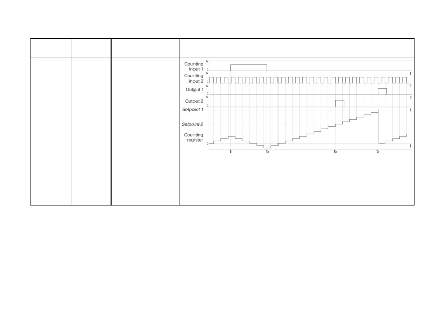
Table 7.1 (continued)
Name of
Input
Principle of
Illustration
the mode
functions
operation
Input 3 -
• if the setpoints
reset
have the same
Input 4 -
sign, counter resets
block
after reaching the
setpoint, that is
larger by module.
{t1-t2} - the decrease in the value of the counting register (impulse
appears at the counting input 2);
t3 - moment of switching of output 2 in case of coincidence of values of
the counting register and setpoint 2;
t4 - moment of switching of output 1 in case of coincidence of values of
the counting register and setpoint 1
45
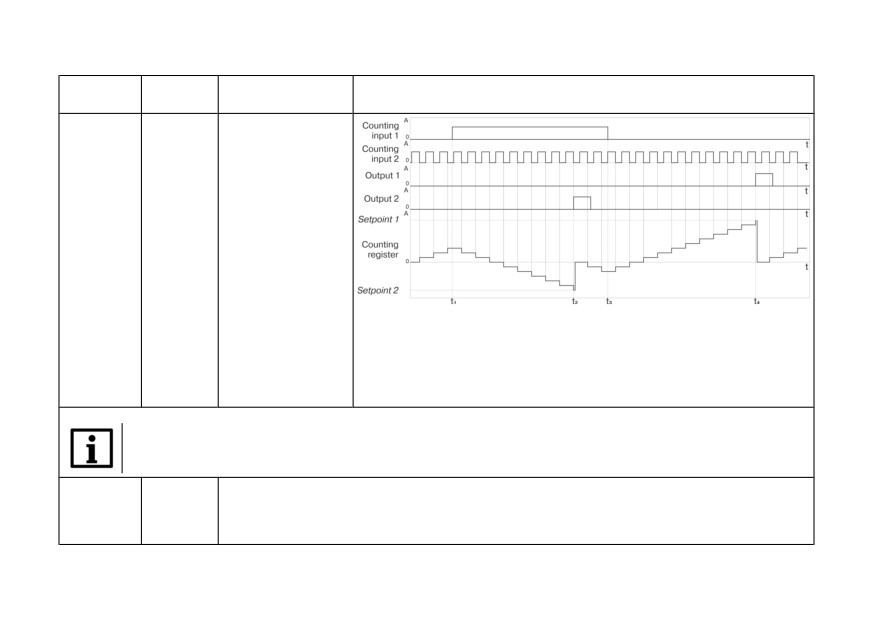
Table 7.1 (continued)
Name of
Input
Principle of
Illustration
the mode
functions
operation
• if the setpoints
have different
signs, the counter
is reset after
reaching each
value
{t1-t3} - the decrease in the value of the counting register (impulse
appears at the counting input 2);
t2 - moment of switching of output 2 in case of coincidence of values of
the counting register and setpoint 2;
t4 - moment of switching of output 1 in case of coincidence of values of
the counting register and setpoint 1
NOTICE
If the setpoint is set as zero, it is considered to be disabled, and the counter does not use it.
Individual
Input 1 -
Two counting inputs are used: pulses on Input 1 increase the value of the counting register,
count
count 1
and the pulses on Input 2 decrease it. In this case, two setpoints are used (after reaching
(inP = 4)
Input 2 -
each of them, the corresponding output switches):
count 2
46
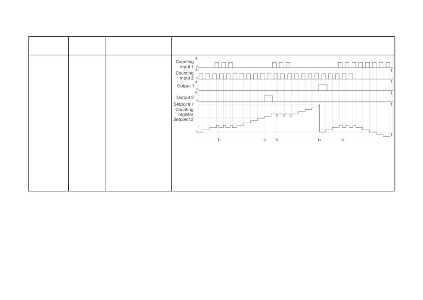
Table 7.1 (continued)
Name of
Input
Principle of
Illustration
the mode
functions
operation
Input 3 -
• if both setpoints
reset
have the same
Input 4 -
sign, counter does
block
not reset after
reaching lesser (by
module) value.
Otherwise,
corresponding
output is switched
each time counter
reaches this
setpoint, regardless
t1, t3, t5 - moments of the decrease in the value of the counting register
of the direction of
(impulse appears at the counting input 2);
the count
t2 - moment of switching of output 2 in case of coincidence of values of
the counting register and setpoint 2;
t4 - moment of switching of output 1 in case of coincidence of values of
the counting register and setpoint 1
47
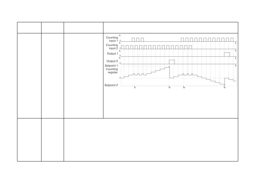
Table 7.1 (continued)
Name of
Input
Principle of
Illustration
the mode
functions
operation
• if the setpoints
have different signs
(the first is greater
than zero, and the
second is smaller),
then counter resets
after reaching each
setpoints
t1, t3 - moments of the decrease in the value of the counting register
(the appearance of the pulse at the counting input 2);
t2 - moment of switching of output 2 in case of coincidence of values of
the counting register and setpoint 2;
t4 - moment of switching of output 1 in case of coincidence of values of
the counting register and setpoint 1
Reversing
Input 1 -
After the power is on, the device is in the "count-up" mode by default. For reversing count it
count
count
is necessary to apply signal to input 2.
(inP = 5)
Input 2 -
Thus there are two counting inputs: pulses on Input 1, lead to an increase in the value of the
change
counter, the counting direction is changed cyclically with each incoming pulse on Input 2. In
counting
this case, two setpoints are used (after reaching each of them, the corresponding output
direction
switches):
(reverse)
Input 3 -
reset
48
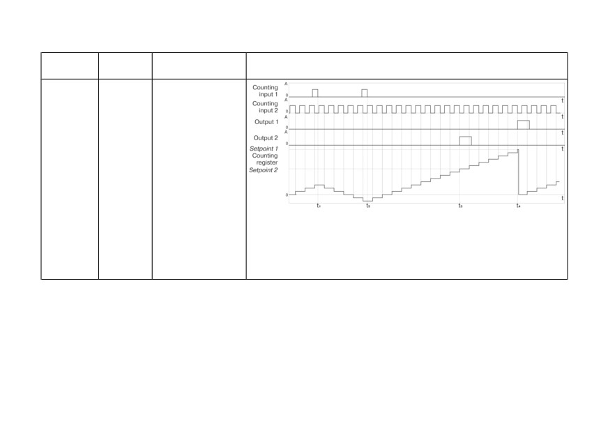
Table 7.1 (continued)
Name of
Input
Principle of
Illustration
the mode
functions
operation
Input 4 -
• if both the
block
setpoints have the
same sign
t1, t2 - moments of change of the counting direction (the appearance of
the pulse at the counting input 2);
t3 - moment of switching of output 2 in case of coincidence of values of
the counting register and setpoint 2;
t4 - moment of switching of output 1 in case of coincidence of values of
the counting register and setpoint 1
49
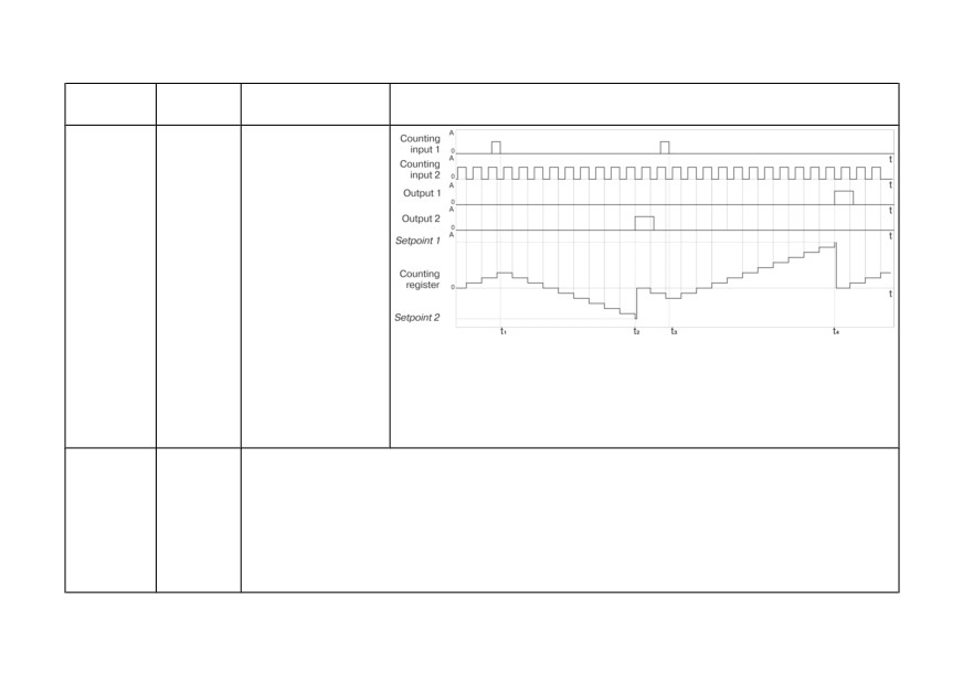
Table 7.1 (continued)
Name of
Input
Principle of
Illustration
the mode
functions
operation
• if the setpoints
have different signs
t1, t3 - moments of change of the counting direction (the appearance of
the pulse at the counting input 2);
t2 - moment of switching of output 2 in case of coincidence of values of
the counting register and setpoint 2;
t4 - moment of switching of output 1 in case of coincidence of values of
the counting register and setpoint 1
Quadrature
Input 1 -
The counting direction is determined by the meanders that come on two inputs. If the first
/ operation
count 1
meander is ahead of the second one, the counter counts the pulses at the first input in the
with
Input 2 -
increase mode, and if it lags - in the decrease mode. In this case, two setpoints are used
encoders
count 2
(after reaching each of them, the corresponding output switches):
(inP = 6)
Input 3 -
reset
Input 4 -
block
50
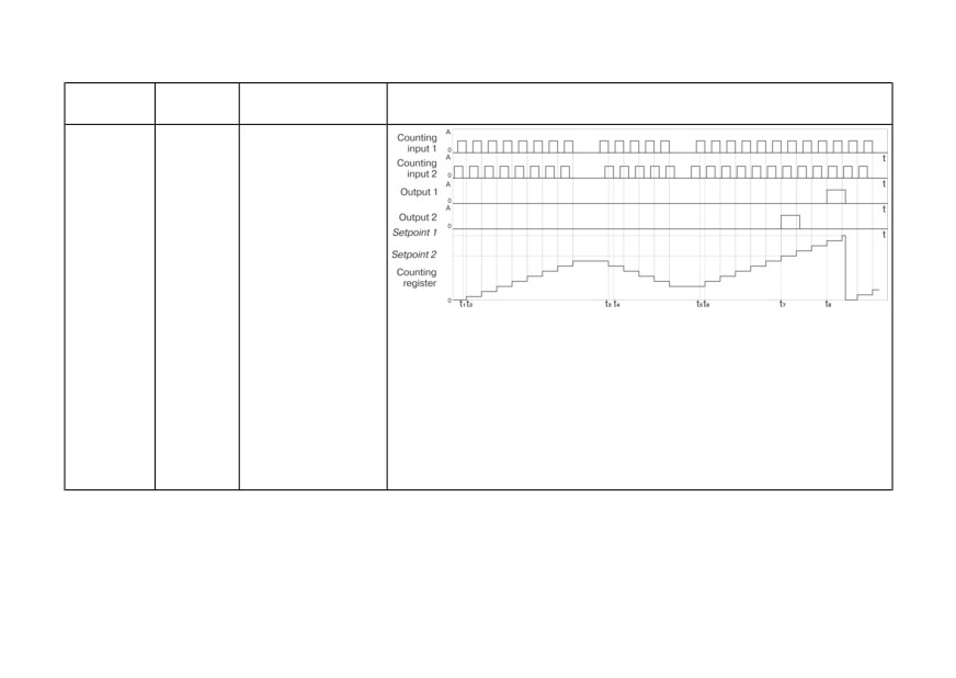
Table 7.1 (continued)
Name of
Input
Principle of
Illustration
the mode
functions
operation
• if both the
setpoints have the
same sign
t1, t2, t5, t6 - meander at input 1 is ahead of the meander at the input 2,
the counter counts in the mode of increasing the value of the count
register;
t3, t4 - the meander at input 1 lags behind the meander at input 2,
the counter counts in the mode of decreasing the value of the counting
register;
t7 - moment of switching of output 2 for the time of exceeding the value
of setpoint 2 by the counting register;
t8 - moment of switching of output 1 for the time of exceeding the value
of setpoint 1 by the counting register
51
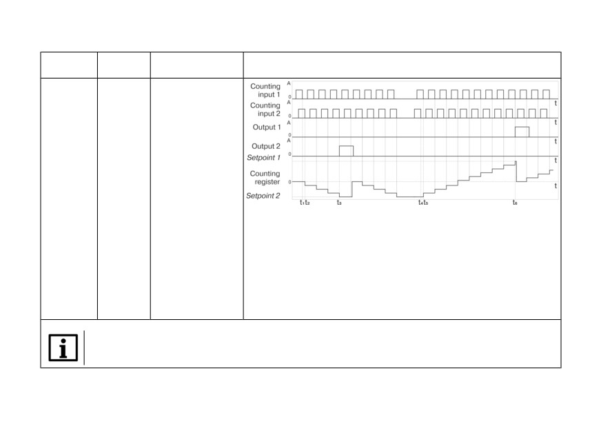
Table 7.1 (continued)
Name of
Input
Principle of
Illustration
the mode
functions
operation
• if setpoints have
different signs
t1, t2 - the meander at input 1 lags behind the meander at input 2,
the counter counts in the mode of increasing the value of the count
register;
t3 - moment of switching of output 2 in case of coincidence of values of
the counting register and the setpoint 2;
t4, t5 - the meander at input 1 is ahead of the meander at input 2,
the counter counts in the mode of increasing the value of the count
register;
t6 - moment of switching of output 1 in case of coincidence of values of
the counting register and the setpoint 1
NOTICE
After reaching the physical limit of the count (if the counter does not reset after reaching the setpoint), the
device transfers the overflow result and continues the count.
52
7.3 Configuring the device from PC
Device can be configured from PC by using RS-485 and USB communication interfaces. It supports
three communication protocols: OWEN, MODBUS RTU и MODBUS ASCII. Addresses, names,
dimensionalities, hash-codes and other configuration parameters are given in Appendix A.
Functions of the software "Configurator СИ30" (file cfgSI30.exe), which is designed for configuring the
device with PC, are described in the user manual "Pulse counter, model СИ30. Configuration" on the
Parameters for reading indications of the counter from PC are described in Table A.2.
8 Maintenance
Safety measures (see section 3) should be observed during the maintenance.
Maintenance of the device has to be carried out at least once in 6 months and includes the following
procedures:
• checking the mounting of the device;
• checking the screw connections;
• removing dust and dirt from the terminal block of the device.
9 Marking
The housing of the device is marked with:
• name of the device;
• protection class of the housing according to GOST 14254;
• voltage and frequency of supply;
53
• power consumption;
• class of protection against electric shock according to GOST 12.2.007.0;
• sign of type approval for measuring devices;
• EAC sign;
• country of origin;
• serial number of the device and the year of manufacture.
Consumer packaging is marked with:
• name of the device;
• EAC sign;
• country of origin;
• serial number of the device and the year of manufacture.
10 Packaging
Device should be packed according to GOST 23088-80 into consumer packaging, made of paperboard
(according to GOST 7933-89).
Packaging of the device for mail delivery is performed according to GOST 9181-74.
11 Transportation and storage
The device should be transported in closed vehicles of any kind. Packages should be fixed for
transportation according to rules for corresponding type of vehicle.
Transport conditions must comply with conditions 5 in GOST 15150-69 (ambient temperature from
minus 25 to +55 °C with observance of protection measures against impacts and vibrations).
54
Transportation should be carried out in individual packaging or in containers.
Storage conditions in containers on the warehouse of the manufacturer and consumer must correspond
to conditions 1 in GOST 15150-69. The air must not contain aggressive admixtures.
The device should be stored on racks.
12 Scope of delivery
Item
Quantity
The device
1 piece
Passport and warranty card
1 piece
User manual
1 piece
The verification procedure (at the request of the
1 piece
customer)
Fasteners
1 set
CD with the software
1 piece
NOTICE
The manufacturer reserves the right to make additions to the contents of the device.
13 Warranty
The manufacturer guarantees conformity of the device to requirements of technical conditions (ТУ)
under the conditions of operation, transportation, storage and installation.
55
Warranty period of operation - 24 months from the date of sale.
In case of failure of the device during the warranty period at observance of conditions of operation,
transportation, storage and installation the manufacturer undertakes to provide free repair or
replacement.
Sequence of transmitting the device to service center is written in the passport and in the warranty card.
56
Appendix A. Device parameters
Table A.1 - Configurable parameters
Parameter
Modbus
Modbus
Hash-
Format,
Range of values and
name and
function
Factory settings
address
code
data size
indication
designation
Write / Read
Setpoint 1
0×000C
0×06, 0×10 /
Long
from minus 99999
0×FA1E
999999
U1
0×000D
0×03
(4 bytes)
to 999999
Setpoint 2
0×000E
0×06, 0×10 /
Long
from minus 99999
0×9707
0
U2
0×000F
0×03
(4 bytes)
to 999999
0 - Count-up (1)
1 - Count-down (2)
Counting mode
0×06, 0×10 /
Word
2 - Command (3)
0×0008
0×38D9
Count-up
inP
0×03
(2 bytes)
3 - Individual (4)
4 - Reversing (5)
5 - Quadrature (6)
0 - Switched after
setpoint (1)
1 - Switched before
setpoint (2)
Output mode
0×06, 0×10 /
Word
0×0009
0×D11F
2 - Switched for a time
Switched after setpoint
oUt
0×03
(2 bytes)
after the setpoint (3)*
3 - Switched when
multiple setpoint
values (4)
57
Table A.1 (continued)
Parameter
Modbus
Modbus
Hash-
Format,
Range of values and
name and
function
Factory settings
address
code
data size
indication
designation
Write / Read
NOTICE
* After reaching the setpoint the output is switched for a time period, that is specified in parameteres t1
and t2, the count value is reset and the counting continues from zero (parameter SPM = RESET).
Time period for
Unsigned
0×0010
0×06, 0×10 /
output 1
0×2E75
long
from 0 to 999990 ms
1000 ms
0×0011
0×03
t1
(4 bytes)
Time period for
Unsigned
0×0012
0×06, 0×10 /
output 2
0×436C
long
from 0 to 999990 ms
1000 ms
0×0013
0×03
t2
(4 bytes)
0
(————)
1
(———.-)
Decimal point
position
0×06, 0×10 /
Word
2
(——.-)
0×0014
0×6ABF
0
multiplier
0×03
(2 bytes)
3
(—.—)
FDP
4
(-.——)
5
(-.———)
Unsigned
Multiplier
0×0015
0×06, 0×10 /
0×3085
long
from 0.00001 to 99999
1
F
0×0016
0×03
(4 bytes)
0
(————)
Position of the
0×06, 0×10 /
Word
decimal point
0×0007
0×B3EB
1
(———.-)
0
0×03
(2 bytes)
DP
2
(——.-)
58

Table A.1 (continued)
Parameter
Modbus
Modbus
Hash-
Format,
Range of values and
name and
function
Factory settings
address
code
data size
indication
designation
Write / Read
3
(—.—)
4
(-.——)
0 - Continue counting
without resetting
(CONT)
Type of work
1 - Stop the counting
after reaching
0×06, 0×10 /
Word
Continue counting
0×000A
0×69B2
until a "RESET" signal
setpoint
0×03
(2 bytes)
without resetting
(STOP)
SPM
2 - Reset the counter
and continue counting
(RESET)
0 - Reset the counter
(1)
1 - Reset the counter
and disable output
Type of work to
signals (2)
0×06, 0×10 /
Word
"Reset" signal
0×000B
0×4C9A
2 - Reset the counter
Reset the counter
0×03
(2 bytes)
rSt
and wait for signal
"Start" (3)
3 - Reset the counter
and wait for signal
"Stop" (4)
59

Table A.1 (continued)
Parameter
Modbus
Modbus
Hash-
Format,
Range of values and
name and
function
Factory settings
address
code
data size
indication
designation
Write / Read
Frequency of
0×06, 0×10 /
Word
the input filter
0×0017
0×9FE6
from 1 to 50000 Hz
50000 Hz
0×03
(2 bytes)
FREQ
Minimum
duration of the
Unsigned
0×0018
0×06, 0×10 /
from 10 to 9999990
signal on the
0×5C98
long
10 microseconds
0×0019
0×03
microseconds
control inputs
(4 bytes)
Cnt.t
Input logic1)
0 - nPn
(type of input
0×06, 0×10 /
Word
0×001D
0×601C
nPn
signal)
0×03
(2 bytes)
1 - PnP
SiG
Brightness of
0×06, 0×10 /
Word
the indicator
0×001C
0×0AE6
from 0 to 3 (1 - 4)
3
0×03
(2 bytes)
brHt
0 - Buttons unlocked
(oFF)
1 - Blocked counter
Lock buttons
0×06, 0×10 /
Word
0×001A
0×E954
reset (1)
Buttons unlocked
LoCK
0×03
(2 bytes)
2 - Change of
setpoints is blocked
(2)
60
Table A.1 (continued)
Parameter
Modbus
Modbus
Hash-
Format,
Range of values and
name and
function
Factory settings
address
code
data size
indication
designation
Write / Read
3 - Reset and change
of setpoints are
blocked (3)
Restore factory
settings
-
-
-
-
YES / no
-
dEFAUL
Password
0×06, 0×10 /
Word
0×001E
0×2728
from 0000 to 9999
0000
PASS
0×03
(2 bytes)
Displayed
0 - Setpoint 1
0×06, 0×10 /
Word
setpoint2)
0×001B
0×CAA0
0
0×03
(2 bytes)
1 - Setpoint 2
ind2
1 - Exit with saving
Command for
applying
2 - Exit without saving
-
-
-
-
-
settings2)
3 - Return to factory
APPL
settings
RS-485 settings
0 - 2400
1 - 4800
RS-485 data
2 - 9600
0×06, 0×10 /
Word
transfer rate
0×0000
0×B760
9600
0×03
(2 bytes)
3 - 14400; 4 - 19200
bPS
5 - 28800; 6 - 38400
7-57600;8-115200
61
Table A.1 (continued)
Parameter
Modbus
Modbus
Hash-
Format,
Range of values and
name and
function
Factory settings
address
code
data size
indication
designation
Write / Read
Data word
0 - 7 bit (7 bit)
0×06, 0×10 /
Word
length
0×0001
0×523F
8 bit
0×03
(2 bytes)
1 - 8 bit (8 bit)
LEn
0 - Without parity (NO)
Parity
0×06, 0×10 /
Word
1 - Even parity
0×0002
0×E8C4
Without parity
PrtY
0×03
(2 bytes)
(EVEN)
2 - Odd parity (Odd)
Number of stop
0 - 1 stop bit
0×06, 0×10 /
Word
bits
0×0003
0×B72E
1 stop bit
0×03
(2 bytes)
1 - 2 stop bits
Sbit
from 0 to 255 when
Base address
0×06, 0×10 /
Word
A.Len = 8
of the device3)
0×0005
0×9F62
16
0×03
(2 bytes)
from 0 до 2047 when
Addr
A.Len = 11
62

Table A.1 (continued)
Parameter
Modbus
Modbus
Hash-
Format,
Range of values and
name and
function
Factory settings
address
code
data size
indication
designation
Write / Read
Length of
8 bit
network
0×06, 0×10 /
Word
0×0004
0×1ED2
8 bit
address2)
0×03
(2 bytes)
11 bit
A.LEN
Response
delay
0×06, 0×10 /
Word
0×0006
0×CBF5
from 0 to 45
0
RS-485
0×03
(2 bytes)
rS.dL
Notes
1) Setting of parameter SiG works only together with DIP switch (see section 5.4).
2) Parameters that are not displayed in the Setup mode of the device.
3) In Modbus protocol address 0 is reserved for broadcast packages. In OWEN protocol address 255 is reserved for
broadcast packages.
Table A.2 - Readable parameters
Modbus
Designation and
Modbus
function
Hash-code
Format and size of data
Note
parameter name
address
Read-only
Current value of
0×0000
the pulse counter
0×04
0×A158
Long (4 bytes)
-
0×0001
Ctr
Current counter
0×0002
value in physical
0×04
0×B8BC
Long (4 bytes)
-
0×0003
units CEU
63

Table A.2 (continued)
Modbus
Designation and
Modbus
function
Hash-code
Format and size of data
Note
parameter name
address
Read-only
Current status of
0 - start;
the "Start/stop"
0×0004
0×04
0×6577
-
1 - stop
StSt
0 - count (password not
required);
Current mode
1 - setup from the
(count, setup)
0×0005
0×04
0×CC41
Word (2 bytes)
device's buttons;
CUR
2 - setup from the PC;
3 - count (requires
password)
Network error
code on last
From 0 to 255.
access
0×0006
0×04
0×0233
Word (2 bytes)
After turning on the
to the device
device - 0
n.Err
Name of the
0×0007
ASCII string
device
0×04
0×D681
-
0×0008
(4 bytes)
DEV
X.YY,
Software version
0×0009
ASCII string
where Х - number of
0×04
0×2D5B
VER
0×000А
(4 bytes)
version, YY - number of
subversion
64
Table A.3 - Bit parameters
Designation and
Modbus function
Format and size
name of
Modbus address
Hash-code
Note
write / read
of data
parameter
Digital inputs
Current status of
Byte (1 byte)
the "Reset" input
0×0000
- / 0×02
0×C010
-
0/1
rSti
Current status of
Byte (1 byte)
the "Block" input
0×0001
- / 0×02
0×93EC
-
0/1
Loci
Digital outputs
Status of output 1
Byte (1 byte)
0×0000
- / 0×01
0×6FFD
-
OSt1
0/1
Status of output 2
Byte (1 byte)
0×0001
- / 0×01
0×52A1
-
OSt2
0/1
Reset of counter
0×05, 0×0F /
Byte (1 byte)
0 - no action;
0×0002
0×DF1F
rStC
0×01
0/1
1-reset
65

Table A.3 (continued)
Designation and
Modbus function
Format and size
name of
Modbus address
Hash-code
Note
write / read
of data
parameter
Enable/disable
the program
control mode
0 - OFF (0x0000);
0×0003
0×05 / -
-
-
counter START/
1 - ON (0xFF00)
STOP
OnOff
Command to set
the program
0 - STOP
control mode
(0x0000);
0×0004
0×05 / -
-
-
counter START/
1 - START
STOP
(0xFF00)
PStSt
66