Kawasaki Ninja ZX-10R Motorcycle. Owner's manual (2008-2010 year)
Whenever you see the symbols
CAUTION
shown below, heed their instructions!
This caution symbol identifies
Always follow safe operating and main-
special instructions or proce-
tenance practices.
dures which, if not strictly ob-
served, could result in damage
WARNING
to or destruction of equipment.
This warning symbol identifies
special instructions or proce-
NOTE
dures which, if not correctly fol-
lowed, could result in personal
żThis note symbol indicates points of
injury, or loss of life.
particular interest for more efficient
and convenient operation.
(Australian model only)
TAMPERING WITH NOISE CONTROL SYSTEM
PROHIBITED
Owners are warned that the law may prohibit:
(a) The removal or rendering inoperative by any person other than for purposes
of maintenance, repair or replacement, of any device or element of design
incorporated into any new vehicle for the purpose of noise control prior to
its sale or delivery to the ultimate purchaser or while it is in use; and
(b) the use of the vehicle after such device or element of design has been re-
moved or rendered inoperative by any person.
FOREWORD
Congratulations on your purchase of a new Kawasaki motorcycle. Your new mo-
torcycle is the product of Kawasaki’s advanced engineering, exhaustive testing,
and continuous striving for superior reliability, safety and performance.
Please read this Owner’s Manual carefully before riding so that you will be
thoroughly familiar with the proper operation of your motorcycle’s controls, its fea-
tures, capabilities, and limitations. This manual offers many safe riding tips, but its
purpose is not to provide instruction in all the techniques and skills required to ride
a motorcycle safely. Kawasaki strongly recommends that all operators of this vehi-
cle enroll in a motorcycle rider training program to attain awareness of the mental
and physical requirements necessary for safe motorcycle operation.
To ensure a long, trouble-free life for your motorcycle, give it the proper care and
maintenance described in this manual. For those who would like more detailed in-
formation on their Kawasaki Motorcycle, a Service Manual is available for purchase
from any authorized Kawasaki motorcycle dealer. The Service Manual contains de-
tailed disassembly and maintenance information. Those who plan to do their own
work should, of course, be competent mechanics and possess the special tools
described in the Service Manual.
Keep this Owner’s Manual aboard your motorcycle at all times so that you can
refer to it whenever you need information.
TABLE OF CONTENTS
SPECIFICATIONS
8
Passing Button:
48
LOCATION OF PARTS
13
LAP Button:
48
LOADING AND ACCESSORIES
Brake Lever Adjuster
48
INFORMATION
16
Fuel Tank Cap
49
GENERAL INFORMATION
19
Fuel Tank
50
Meter Instruments
19
Fuel Requirement:
51
Tachometer:
20
Side Stand
52
Digital Meter:
21
Seat Lock
53
Warning/Indicator Lights:
33
Helmet Hooks
58
Key
40
Tool Kit
59
Ignition Switch/Steering Lock
44
Air Cleaner Intake
59
Right Handlebar Switches
45
BREAK-IN
60
Engine Stop Switch:
45
HOW TO RIDE THE MOTORCYCLE .
62
Starter Button:
46
Starting the Engine
62
START/STOP Switch (Stop
Jump Starting
65
Watch):
46
Moving Off
67
Left Handlebar Switches
47
Shifting Gears
68
Dimmer Switch:
47
Braking
69
Turn Signal Switch:
48
Stopping the Engine
71
Horn Button:
48
Stopping the Motorcycle in an
Throttle Control System
112
Emergency
71
Engine Vacuum Synchronization
115
Parking
72
Idle Speed
115
Catalytic Converter
74
Clutch
117
SAFE OPERATION
76
Drive Chain
119
Safe Riding Technique
76
Brakes
129
Daily Safety Checks
78
Brake Light Switches
133
Additional Considerations for High
Steering Damper
135
Speed Operation
80
Front Fork
136
MAINTENANCE AND ADJUSTMENT
82
Rear Shock Absorber
141
Periodic Maintenance Chart
83
Wheels
145
Engine Oil
93
Battery
150
Cooling System
98
Headlight Beam
156
Spark Plugs
104
Fuses
157
Valve Clearance
105
Cleaning Your Motorcycle
159
Kawasaki Clean Air System
105
STORAGE
165
Exhaust Device
106
ENVIRONMENTAL PROTECTION
168
Air Cleaner
107
LOCATION OF LABELS
169
8 SPECIFICATIONS
SPECIFICATIONS
PERFORMANCE
Maximum Horsepower
138.3 kW (188.1 PS) @12 500 r/min (rpm)
(MY)
119.2 kW (162.1 PS) @10 000 r/min (rpm)
Maximum Torque
113 N·m (11.5 kgf·m, 83.3 ft·lb) @8 700 r/min (rpm)
(MY)
113 N·m (11.5 kgf·m, 83.3 ft·lb) @8 700 r/min (rpm)
Minimum Turning Radius
3.4 m (134 in.)
DIMENSIONS
Overall Length
2 110 mm (83.1 in.)
Overall Width
710 mm (28.0 in.)
Overall Height
1 135 mm (44.7 in.)
Wheelbase
1 415 mm (55.7 in.)
Road Clearance
125 mm (4.9 in.)
Curb Mass
208 kg (459 lb)
SPECIFICATIONS 9
ENGINE
Type
DOHC, 4-cylinder, 4-stroke, liquid-cooled
Displacement
998 cm³ (60.9 cu in.)
Bore × Stroke
76.0 × 55.0 mm (3.0 × 2.2 in.)
Compression Ratio
12.9 : 1
Starting System
Electric starter
Cylinder Numbering Method
Left to right, 1-2-3-4
Firing Order
1-2-4-3
Carburetion System
FI (Fuel Injection)
Ignition System
Battery and coil (transistorized ignition)
Ignition Timing (Electronically
10° BTDC @1 100 r/min (rpm)
advanced)
Spark Plugs
NGK CR9EIA-9
Lubrication System
Forced lubrication (wet sump)
Engine Oil
Type:
API SE, SF or SG
API SH, SJ or SL with JASO MA, MA1 or MA2
SAE 10W-40
10 SPECIFICATIONS
Capacity:
4.0 L (4.2 US qt)
Coolant Capacity
2.9 L (3.1 US qt)
TRANSMISSION
Transmission Type
6-speed, return shift
Clutch Type
Wet, multi disc
Driving System
Chain drive
Primary Reduction Ratio
1.611 (87/54)
Final Reduction Ratio
2.412 (41/17)
Overall Drive Ratio
5.068 (Top gear)
Gear Ratio
1st
2.600 (39/15)
2nd
2.053 (39/19)
3rd
1.737 (33/19)
4th
1.550 (31/20)
5th
1.400 (28/20)
6th
1.304 (30/23)
SPECIFICATIONS 11
FRAME
Castor
25.5°
Trail
110 mm (4.3 in.)
Tire Size:
Front
120/70ZR17 M/C (58 W)
Rear
190/55ZR17 M/C (75 W)
Rim Size:
Front
17 × 3.50
Rear
17 × 6.00
Fuel Tank Capacity
17 L (4.5 US gal)
ELECTRICAL EQUIPMENT
Battery
12 V 10 Ah
Headlight
High beam
12 V 55 W + 65 W
Low beam
12 V 55 W + 55 W
LED Tail/Brake Light
0.5/4.1 W
12 SPECIFICATIONS
MY: Malaysia model
Even if one of LED (Light Emitting Diode) tail/brake light is not lit, consult with an
authorized Kawasaki dealer.
Specifications subject to change without notice, and may not apply to every country.
LOCATION OF PARTS 13
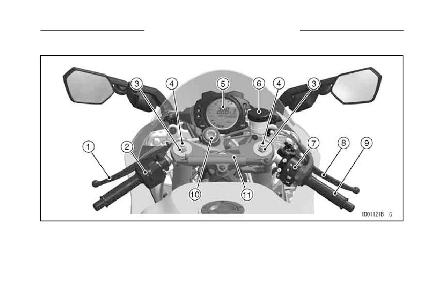
LOCATION OF PARTS
1. Clutch Lever
6. Brake Fluid Reservoir (Front)
2. Left Handlebar Switches
7. Right Handlebar Switches
3. Spring Preload Adjuster
8. Front Brake Lever
4. Rebound Damping Force Adjuster
9. Throttle Grip
(Front Fork)
10. Ignition Switch/Steering Lock
5. Meter Instruments
11. Steering Damper
14 LOCATION OF PARTS
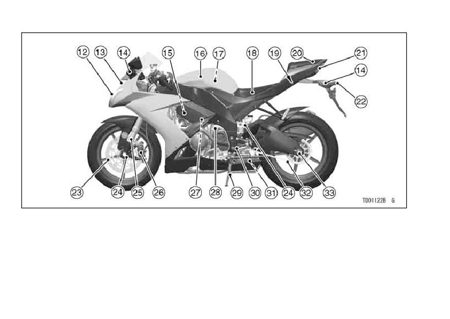
12. Headlight
21. Tail/Brake Light
28. Idle Adjusting Screw
13. Air Cleaner Intake
22. License Plate Light
29. Side Stand
14. Turn Signal Light
23. Brake Disc
30. Shift Pedal
15. Spark Plugs
24. Compression
31. Rebound Damping
16. Fuel Tank
Damping Force
Force Adjuster
17. Air Cleaner
Adjuster
32. Drive Chain
18. Rider’s Seat
25. Front Fork
33. Chain Adjuster
19. Seat Lock
26. Brake Caliper
20. Passenger’s Seat
27. Coolant Reserve Tank
LOCATION OF PARTS 15
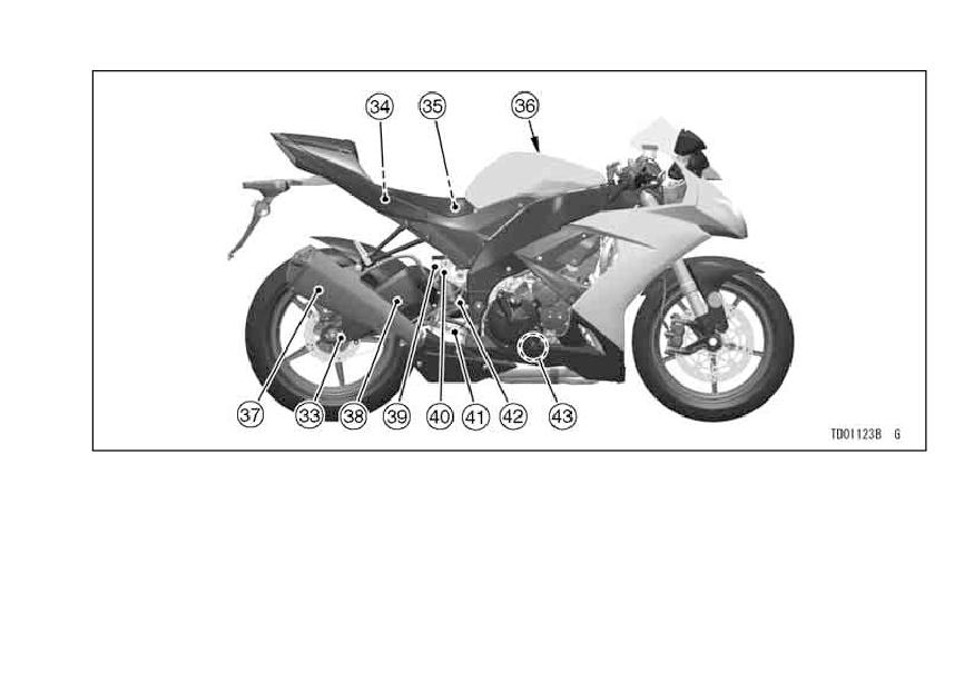
34. Fuse Box
39. Brake Fluid Reservoir (Rear)
35. Battery
40. Rear Shock Absorber
36. Fuel Tank Cap
41. Rear Brake Pedal
37. Muffler
42. Rear Brake Light Switch
38. Swingarm
43. Oil Level Gauge
16 LOADING AND ACCESSORIES INFORMATION
LOADING AND ACCESSORIES INFORMATION
WARNING
warranty can negatively affect perfor-
mance, and can even be illegal. In
Incorrect loading, improper in-
selecting and using accessories, and
stallation or use of accessories,
in loading the motorcycle, you are
or modification of your motorcy-
personally responsible for your own
cle may result in an unsafe rid-
safety and the safety of other persons
ing condition. Before you ride
involved.
the motorcycle, make sure that
the motorcycle is not overloaded
NOTE
and that you have followed these
żKawasaki Parts and Accessories
instructions.
have been specially designed for
use on Kawasaki motorcycles. We
With the exception of genuine
strongly recommend that all parts
Kawasaki Parts and Accessories,
and accessories you add to your
Kawasaki has no control over the
motorcycle be genuine Kawasaki
design or application of accessories.
components.
In some cases, improper installation
or use of accessories, or motorcycle
Because a motorcycle is sensitive to
modification, will void the motorcycle
changes in weight and aerodynamic
forces, you must take extreme care
LOADING AND ACCESSORIES INFORMATION 17
in carrying cargo, passengers and/or
3.
All baggage should be carried as
in the fitting of additional accessories.
low as possible to reduce the effect
The following general guidelines have
on the motorcycle center of gravity.
been prepared to assist you in making
Baggage weight should also be dis-
your determinations.
tributed equally on both sides of the
1.
Any passenger should be thor-
motorcycle. Avoid carrying baggage
oughly familiar with motorcycle op-
that extends beyond the rear of the
eration. The passenger can affect
motorcycle.
control of the motorcycle by im-
4.
Baggage should be securely at-
proper positioning during cornering
tached. Make sure that the baggage
and sudden movements. It is impor-
will not move around while you are
tant that the passenger sit still while
riding. Recheck baggage security
the motorcycle is in motion and not
as often as possible (not while the
interfere with the operation of the
motorcycle is in motion) and adjust
motorcycle. Do not carry animals
as necessary.
on your motorcycle.
5.
Do not carry heavy or bulky items on
2.
You should instruct any passenger
a luggage rack. They are designed
before riding to keep his feet on the
for light items, and overloading can
passenger footpegs and hold on to
affect handling due to changes in
the operator, seat strap or grab rail.
weight distribution and aerodynamic
Do not carry a passenger unless he
forces.
or she is tall enough to reach the
footpegs and footpegs are provided.
18 LOADING AND ACCESSORIES INFORMATION
6.
Do not install accessories or carry
designed or installed items can re-
baggage that impairs the perfor-
sult in an unsafe riding condition.
mance of the motorcycle. Make
9. This motorcycle was not intended
sure that you have not adversely
to be equipped with a sidecar or to
affected any lighting components,
be used to tow any trailer or other
road clearance, banking capability
vehicle. Kawasaki does not manu-
(i.e., lean angle), control operation,
facture sidecars or trailers for mo-
wheel travel, front fork movement,
torcycles and cannot predict the ef-
or any other aspect of the motorcy-
fects of such accessories on han-
cle’s operation.
dling or stability, but can only warn
7.
Weight attached to the handlebar or
that the effects can be adverse and
front fork will increase the mass of
that Kawasaki cannot assume re-
the steering assembly and can re-
sponsibility for the results of such
sult in an unsafe riding condition.
unintended use of the motorcycle.
8.
Fairings, windshields, backrests,
Furthermore, any adverse effects on
and other large items have the ca-
motorcycle components caused by
pability of adversely affecting stabil-
the use of such accessories will not
ity and handling of the motorcycle,
be remedied under warranty.
not only because of their weight, but
Maximum Load
also due to the aerodynamic forces
Weight of rider, passenger, baggage,
acting on these surfaces while the
and accessories must not exceed 180 kg
motorcycle is in operation. Poorly
(397 lb).
GENERAL INFORMATION 19
GENERAL INFORMATION
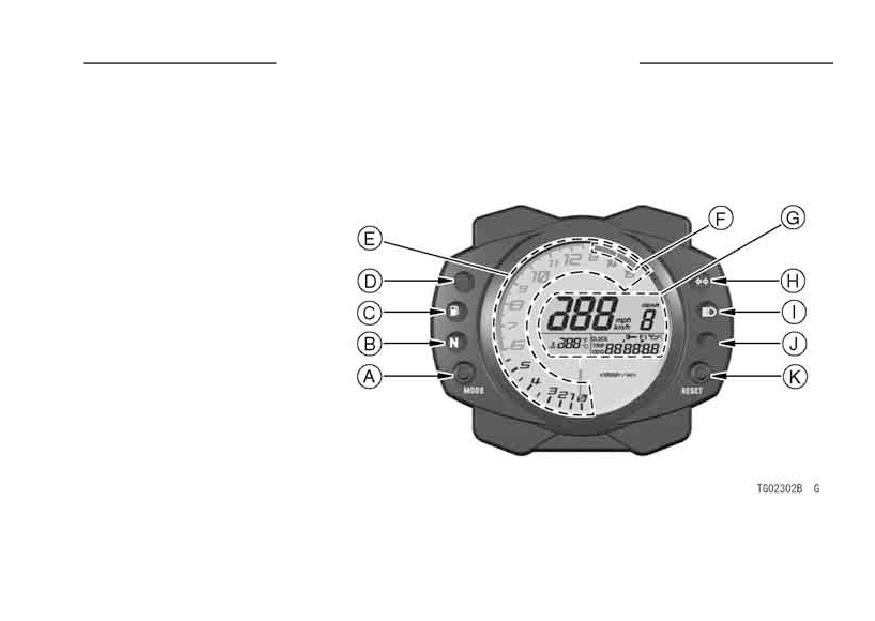
Meter Instruments
A. MODE Button
B. Neutral Indicator Light
C. Fuel Level Indicator Light
D. Shift-Up Indicator Light
E. Tachometer
F. Red Zone
G. Digital Meter
H. Turn Signal Indicator Light
I. High Beam Indicator Light
J. Warning Light
K. RESET Button
20 GENERAL INFORMATION
Tachometer:
NOTE
The tachometer shows the engine
żThe illumination in the meter instru-
speed in revolutions per minute (r/min,
ment can be adjusted at four modes
rpm). On the right side of the tachome-
by pushing RESET button when turn-
ter face is a portion called the “red
ing the ignition key to ON.
zone”.
Engine r/min (rpm) in the
red zone is above maximum recom-
CAUTION
mended engine speed and is also
above the range for good performance.
Engine r/min (rpm) should not
When the ignition key is turned to
be allowed to enter the red zone;
“ON”, the tachometer momentarily
operation in the red zone will
goes from the minimum to the maxi-
overstress the engine and may
mum, then goes back from the maxi-
cause serious engine damage.
mum to the minimum reading to check
its operation. If the tachometer does
not operate correctly, have it checked
by an authorized Kawasaki dealer.
GENERAL INFORMATION 21
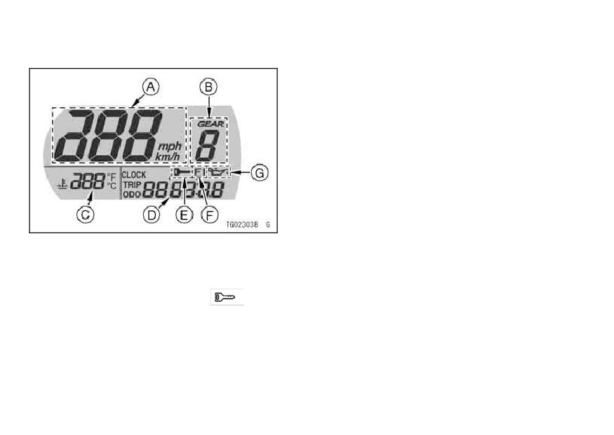
Digital Meter:
The digital meter displays the fol-
lowing functions: the speedometer,
clock, trip meter, odometer, coolant
temperature meter, stop watch, gear
position, oil pressure warning symbol,
A. Odometer
immobilizer warning symbol and fuel
B. Trip meter
injection warning symbol. Pushing the
C. Clock
D. Stop Watch
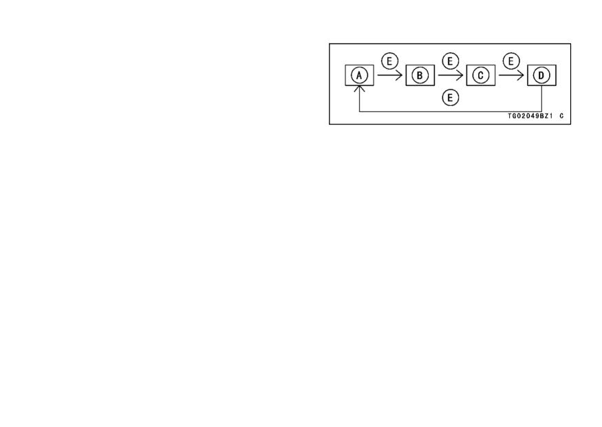
MODE button shifts the display in the
E. Push MODE Button
digital meter through the following four
modes: odometer, trip meter, clock,
and stop watch. When the ignition key
is turned to “ON”, all the LCD segments
are displayed for three seconds, then,
depending on the mode selected, the
clock or meters operate normally.
22 GENERAL INFORMATION
Digital Meter
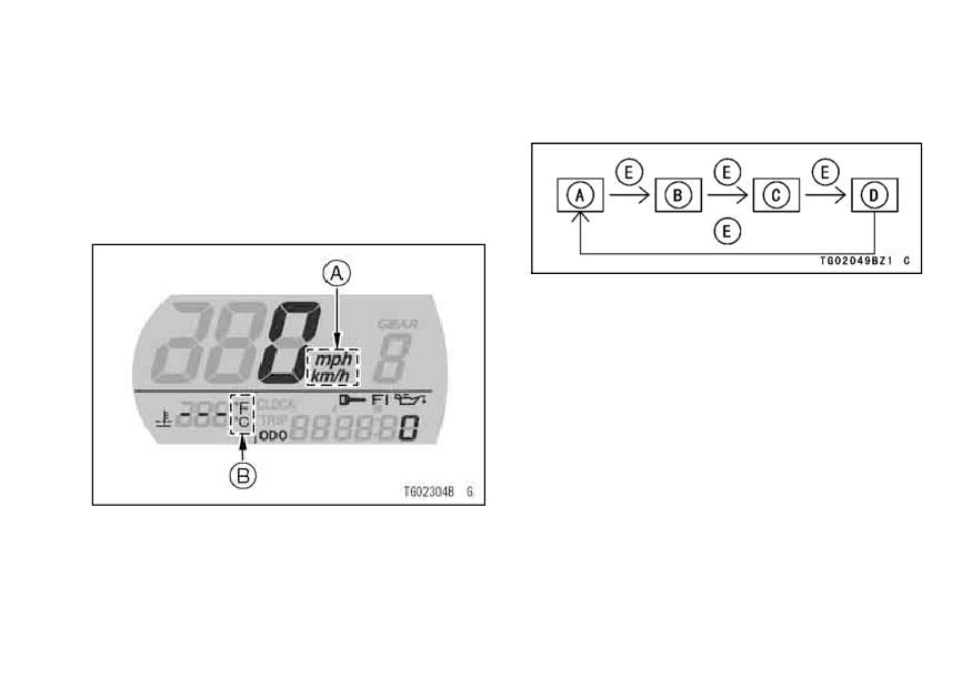
Mile/Km Display -
Mile/Km Display can alternate be-
tween English and metric modes (mile
and km) in the digital meter. Make sure
that km or mile according to local reg-
ulations is correctly displayed before
riding.
NOTE
ż
Do not operate the vehicle with the
digital meter displaying in the wrong
unit (km or mile) of the digital meter.
A. Speedometer
Shift the km/mile display in the digital
B. Gear Position
meter as follows.
C. Lap Counter/Coolant Temperature Meter
D. Clock, Trip Meter, Odometer, Stop Watch
E. Immobilizer Warning Symbol (
)
F. Fuel Injection Warning Symbol (FI)
G. Oil Pressure Warning Symbol
NOTE
żDo not shift the digital meter display
while riding for safe operation.
GENERAL INFORMATION 23
• Display the odometer in the digital
• The km/mile (and °C/°F temperature)
meter.
display shifts as follows.
• The km/mile (or °C/°F temperature)
display shifts by pushing the RE-
SET button while the MODE button
pushed in.
A. Km and °C Display
B. Mile and °F Display
C. Mile and °C Display
D. Km and °F Display
E. Push RESET Button with MODE Button in
NOTE
ż
The data is maintained even if the
battery is disconnected.
A. Km/Mile Display
Speedometer -
B. °C/°F Display
The speedometer shows the speed
of the vehicle in digital values.
24 GENERAL INFORMATION
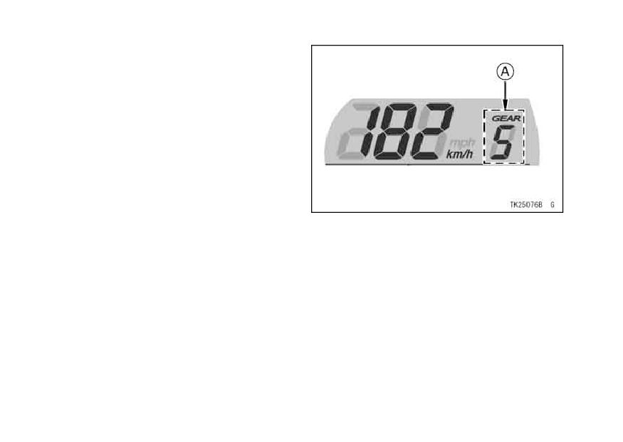
Gear Position -
The gear position shows the cor-
responding gear position where the
transmission is shifted.
1:
When the transmission is in 1st
gear, the “1” is displayed.
When the transmission is in 2nd
2:
gear, the “2” is displayed.
When the transmission is in 3rd
A. Gear Position
3:
gear, the “3” is displayed.
When the transmission is in 4th
NOTE
4:
gear, the “4” is displayed.
żIf the gear position is in the neutral
When the transmission is in 5th
position, the gear position has no dis-
5:
gear, the “5” is displayed.
play. The neutral indicator light is lit.
When the transmission is in 6th
6:
gear, the “6” is displayed.
GENERAL INFORMATION 25
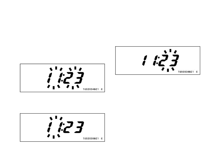
Clock -
• Push the RESET button. The hour
To adjust hours and minutes:
display stops flashing and the minute
display starts flashing.
Push the
• Turn the ignition key to “ON”.
MODE button to advance the min-
• Push the MODE button to display the
clock.
utes.
• Push the RESET button for more
than two seconds. Both the hour and
minute displays start flashing.
• Push the RESET button. Both the
hour and minute displays start flash-
ing again.
• Push the RESET button. The hour
• Push the MODE button. The dis-
display only flashes.
Push the
plays stop flashing and the clock
MODE button to advance the hours.
starts working.
26 GENERAL INFORMATION
NOTE
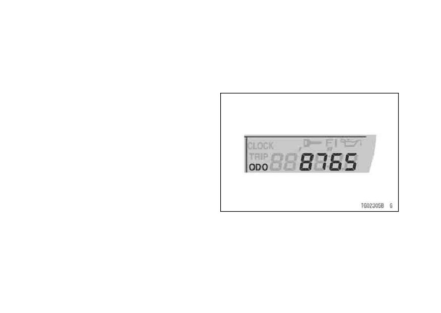
Odometer -
The odometer shows the total dis-
żPushing the MODE button momen-
tance in kilometers or miles that the ve-
tarily advances the hour or minute
hicle has been ridden. This meter can-
step by step. Pushing and hold-
not be reset.
ing the button advances the hour or
minute continuously.
żThe clock works normally from the
back-up power while the ignition
switch is turned off.
żWhen the battery is disconnected,
the clock resets to 1:00 and starts
working again when the battery is
connected.
NOTE
żThe data is maintained even if the
battery is disconnected.
żWhen the figures come to 999999,
they are stopped and locked.
GENERAL INFORMATION 27
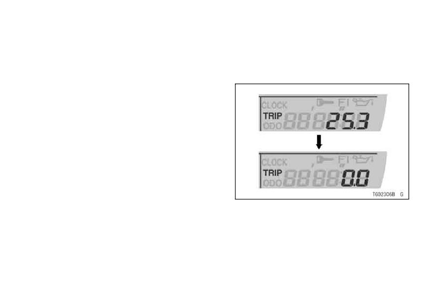
Trip Meters -
• After two second, the figure display
The trip meter shows the distance in
turns to 0.0, and then starts counting
kilometers or miles traveled since it was
when the vehicle is operated. The
last reset to zero.
meter counts until it is next reset.
To reset the trip meter:
• Push the MODE button to display the
trip meter.
• Push the RESET button and hold it
in.
28 GENERAL INFORMATION
NOTE
Lap Counter/Coolant Temperature
Meter -
żThe data is maintained by the back
The Lap counter/coolant temperature
-up power if the ignition key is turned
meter shows either the lap number or
off.
the coolant temperature. The lap num-
żWhen the trip meter reaches 999.9
ber is displayed when in the stop watch
while riding, the meter resets to 0.0
mode.
and continues counting.
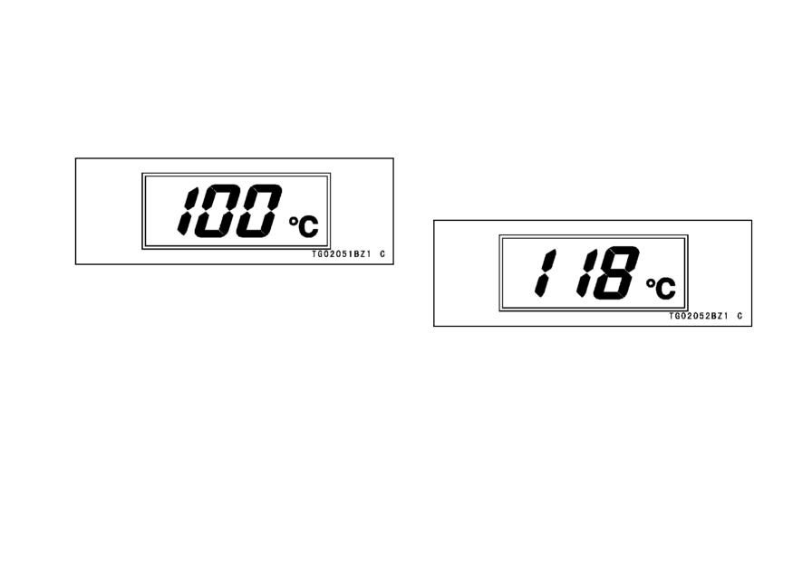
The coolant temperature is displayed
żWhen the battery is disconnected,
as follows.
the meter display resets to 0.0.
• Start the engine. If the coolant tem-
perature is below 40 °C (104 °F), no
temperature is displayed.
GENERAL INFORMATION 29
• When the coolant temperature rises
• If the coolant temperature rises to
to above 40 °C (104 °F), the numer-
above 115 °C (239 °F) and below
ical value of the coolant temperature
120 °C (248 °F), the numerical value
at the present state is displayed.
of the current coolant temperature
starts flashing. This warns the oper-
ator that the coolant temperature is
high.
30 GENERAL INFORMATION
Stop Watch -
• If the coolant temperature rises to
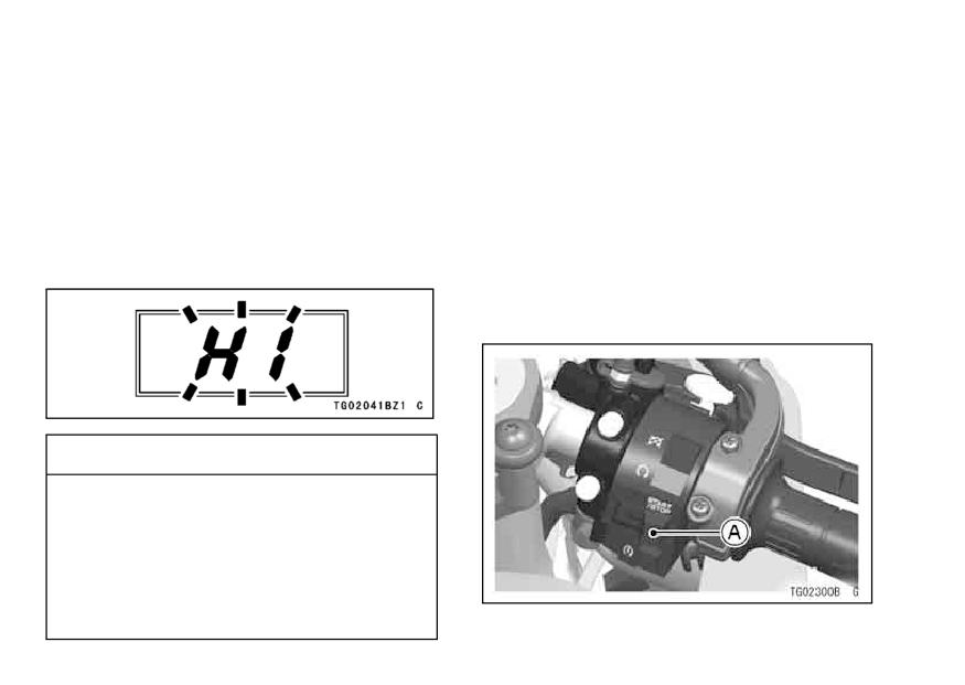
above 120 °C (248 °F), “HI” is dis-
The stop watch can be used in closed
played and starts flashing.
This
course competition.
warns the operator that the coolant
The stop watch is operated as fol-
temperature is too high; stop the
lows;
engine and check the coolant level
• Turn the ignition Key to “ON”.
in the reserve tank after the engine
• Push the MODE button to display the
cools down.
stop watch.
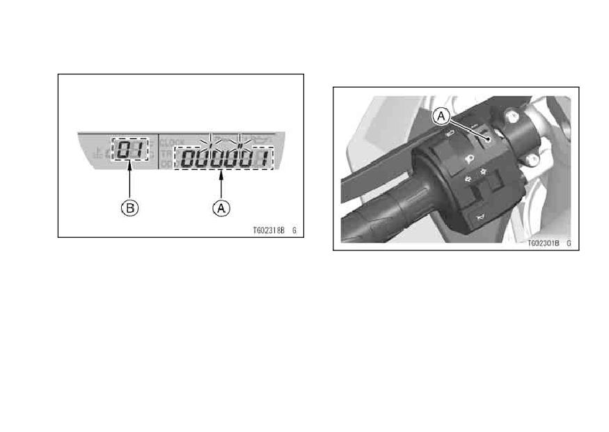
Push the START/STOP switch on the
•
right handlebar switch to the left.
CAUTION
Do not let the engine continue
running when the coolant tem-
perature shows “HI”. Prolonged
engine operation will result in
severe engine damage from
overheating.
A. Start/Stop Switch
GENERAL INFORMATION 31
• The stop watch starts timing laps.
• After each lap, push the LAP button
on the left handlebar switch.
A. Lap Time
B. Lap Number
A. Lap Button

32 GENERAL INFORMATION
• The stop watch starts timing the next
• To stop the stop watch, push the
lap and the previous lap time is dis-
START/STOP switch on the right
played for ten seconds.
handlebar switch to the left.
To display each measured lap time,
•
push the RESET button momentarily.
When no lap number is displayed,
the time displayed is the total time of
all timed laps.
A. Lap Time
B. Lap Number
A. Total Lap Time
GENERAL INFORMATION 33
Warning/Indicator Lights:
• To reset the stop watch and erase all
lap numbers and times, push the RE-
N : When the transmission is in neutral,
SET button for more than two sec-
the neutral indicator light is lit.
onds.
: When the headlight is on high
NOTE
beam, the high beam indicator light is
żIf the coolant temperature rises
lit.
above 115 °C (239 °F) with the Lap
number displayed, the Lap number
: When the turn signal switch is
display in the Lap/Coolant Tempera-
pushed to the left or right, the turn sig-
ture Meter automatically shifts to the
nal indicator light flashes.
coolant temperature meter.
żWhen the battery is disconnected, all
Warning Light: This warning light in
lap numbers and times are reset.
the meter instrument has the three
żThe lap time can be stored for a max-
warning light function: oil pressure
imum of 99 times.
warning light and fuel injection system
warning light and immobilizer system
warning light. This warning light flash
on with the each warning symbols:
engine oil pressure warning symbol
(
)/fuel injection warning sym-
bol (FI)/immobilizer warning symbol
34 GENERAL INFORMATION
(
). If the warning light flashs on
FI: The warning light in the meter in-
with the engine running, have its cause
strument and the fuel injection warn-
checked by an authorized Kawasaki
ing symbol (FI) in the digital meter flash
dealer. Refer to the following each
on whenever the ignition key is turned
to “ON” or trouble occurs in the fuel
symbol instructions
(
), (FI) or
injection system. After turning the ig-
(
) for more detailed information.
nition key to “ON”, the fuel injection
warning symbol (FI) goes off soon af-
: The warning light in the meter
ter it has been ensured that its circuit
instrument and the oil pressure warn-
functions properly. If the warning light
ing symbol (
) in the digital meter
and warning symbol flashs on, have the
flash on whenever the oil pressure is
FI system checked by an authorized
dangerously low or the ignition switch
Kawasaki dealer.
is in the ON position with the engine
not running, and go off when the en-
: The warning light in the meter in-
gine oil pressure is high enough. Re-
strument and the immobilizer warning
fer to the Maintenance and Adjustment
symbol (
) in the digital meter flash
chapter for more detailed engine oil in-
on whenever the ignition key is turned
formation.
to “ON” or trouble occurs in the immo-
bilizer system. After turning the igni-
tion key to “ON”, the immobilizer warn-
ing symbol (
) goes off soon after it
GENERAL INFORMATION 35
has been ensured that its circuit func-
(For models equipped with an
tions properly. If the warning light and
immobilizer system)
warning symbol flashes on, have the
When the key is turned to “OFF”, the
immobilizer system checked by an au-
warning light will start flashing indicat-
thorized Kawasaki dealer.
ing that the immobilizer system is en-
abled. After 24 hours have passed, the
warning light will stop flashing, however
the immobilizer system is still enabled.
Warning light flashes if the improp-
erly coded key is used, or any incor-
rect communication between antenna
and key is occurred. However, when
the properly coded key can be used, or
the communication is clear, the warn-
ing light does not flash.
36 GENERAL INFORMATION
NOTE
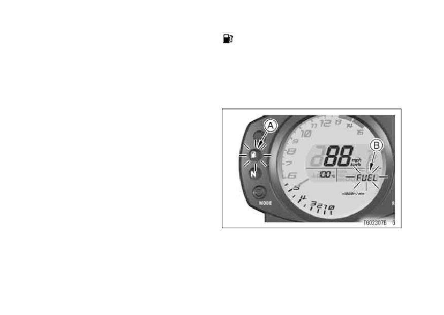
: The fuel level warning light goes on
żWarning light flashing mode can be
and “FUEL” flashes in the digital me-
set to either on or off. Push and
ter, when only 3.7 L (3.9 US qt) of fuel
hold the MODE and RESET buttons
remains. Refuel at the earliest oppor-
simultaneously for more than two
tunity when the fuel level warning light
seconds, within twenty seconds after
goes on and “FUEL” flash.
turning the ignition key to the “OFF”
position, then the warning light will
not flash.
żWhen the battery is connected, warn-
ing light defaults to flashing mode.
żWhen the battery voltage is low (be-
low 12 V), warning light flashing au-
tomatically goes off to prevent exces-
sive battery discharge.
A. Fuel Level Warning Light
B. “FUEL” Flashes
GENERAL INFORMATION 37
NOTE
Shift Up Indicator Light -
The Shift-up indicator light can be
żWhen pushing the MODE button
used in closed course competition. Do
while “FUEL” is displayed, the dis-
not use the shift-up indicator during ev-
play can be shifted to odometer, trip
eryday riding.
meter, or clock mode.
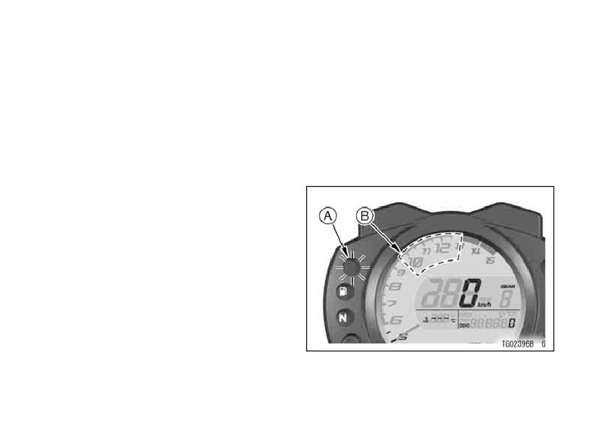
When the engine speed reaches a
pre-set speed, the shift-up indicator
light comes on to indicate the timing for
shifting up to prevent engine damage.
The shift-up indicator light has four
modes, light off, flash, light on (dim)
and light on (bright). The shift-up indi-
cator light timing can be adjusted be-
tween 9 500 r/min (rpm) and 13 000
r/min (rpm).
To select a shift-up indicator light
mode or adjust the shift-up engine
speed setting in the tachometer, do
the following while the motorcycle is
stopped:
38 GENERAL INFORMATION
• Push the MODE and RESET button
• To adjust the shift-up engine speed,
simultaneously for more than 2 sec-
press the RESET button and the shift
onds. The previous shift-up engine
-up engine speed timing advances
speed setting will be displayed in the
in 50 r/min (rpm) increments up to
tachometer gauge.
13 000 r/min (rpm). Once 13 000
r/min (rpm) is reached while advanc-
• To change the shift-up indicator light
mode, push the MODE button and
ing, the reading returns to 9 500 r/min
the shift-up indicator light will shift be-
(rpm) and begins advancing.
tween light off, flash, light on (bright)
and light on (dim). The shift-up en-
gine speed can only be adjusted
when the light is on.
A. Shift Up Indicator Light
B. Adjustable Range
GENERAL INFORMATION 39
WARNING
• To complete the adjustment, push
the MODE button and RESET but-
Failing to properly observe the
ton simultaneously for more than two
road ahead increases the chance
seconds. The tachometer now oper-
of an accident. Do not concen-
ates normally.
trate on the shift-up indicator
light by taking your eyes off the
road, observe using peripheral
vision.
When shifting down to a lower
gear, do not shift at such a high
speed that the engine r/min
(rpm) jumps excessively. Not
only can this cause engine dam-
age, but the rear wheel may skid
and cause an accident. Down-
shifting should be done below
5 000 r/min (rpm) for each gear.
40 GENERAL INFORMATION
NOTE
Key
This motorcycle has a combination
żPushing and holding the RESET but-
key, which is used for the ignition
ton advances the shift-up engine
switch/steering lock, seat lock, and fuel
speed continuously.
tank cap.
żThe data is maintained even if the
battery is disconnected.
(Except for models equipped with an
immobilizer system)
CAUTION
Blank keys are available at your
Kawasaki dealers. Ask your dealer to
Engine r/min (rpm) should not
make any additional spare keys you
be allowed to enter the red zone;
may need, using your original key as a
operation in the red zone will
master.
overstress the engine and may
cause serious engine damage.
Immobilizer System (For models
equipped with an Immobilizer
system)
This motorcycle is equipped with an
immobilizer system to protect your mo-
torcycle from theft. This motorcycle
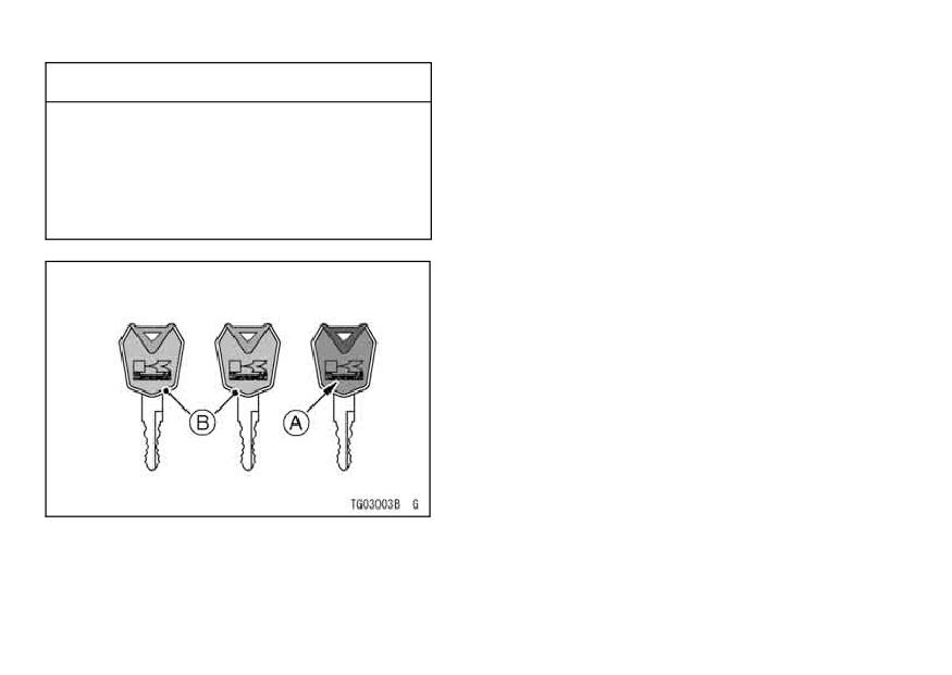
has one master key with a red head
and two user-keys with black heads.
Kawasaki strongly recommends you do
not use the master key for daily driving.
GENERAL INFORMATION 41
Store the master key and the key tag in
CAUTION
a safe place. If the master key is lost,
Do not put two keys of any immo-
registering new codes for replacement
bilizer system on the same key
user keys into the electronic control unit
ring.
is impossible. To make additional user
Do not submerge any key in wa-
keys, take the vehicle along with the
ter.
master key and all user keys to an au-
Do not expose any key to exces-
thorized Kawasaki dealer to have them
sively high temperature.
re-registered. Up to five user keys can
Do not place any key close to
be registered with the immobilizer sys-
magnets.
tem at one time.
Do not place heavy item on any
key.
Do not grind any key or alter its
shape.
Do not disassemble the plastic
part of any key.
Do not drop any key and/or apply
shocks to it.
If a user-key is lost, re-registry
at dealer is securely required to
prevent the possibility of theft.
42 GENERAL INFORMATION
CAUTION
• Master key:
The master key can never be dupli-
If the master key is lost, an au-
cated.
thorized Kawasaki dealer will
have to replace the ECU, order a
• User-keys:
You can register maximum 5 user
new master key, and register the
-keys at one time.
user keys.
If an improperly coded key is used or
any incorrect communication between
ECU and key is occurred, the engine
does not start and warning light flashes.
A properly coded key must be used
or the communication should be clear
for the engine to start.
When the key is turned to “OFF, ” the
warning light will start flashing indicat-
ing that the immobilizer system is en-
abled. After 24 hours have passed, the
warning light will stop flashing, however
A. Master key (red)
the immobilizer system is still enabled.
B. User-keys (black)
GENERAL INFORMATION 43
If the master key is lost, registering
EC Directive Compliance
new user key codes is impossible. If
This immobilizer system complies
all keys are lost, the ECU must be re-
with the R & TTE (Radio equipment and
placed.
telecommunications terminal equip-
ment and the mutual recognition of
NOTE
their conformity) Directive.
żWarning light flashing mode can be
set to either on or off. Push and
hold the MODE and RESET buttons
simultaneously for more than two
seconds, within twenty seconds after
turning the ignition key to the “OFF”
position, then the warning light will
not flash.
żWhen the battery is connected, warn-
ing light defaults to flashing mode.
żWhen the battery voltage is low (be-
low 12 V), warning light flashing au-
tomatically goes off to prevent exces-
sive battery discharge.
44 GENERAL INFORMATION
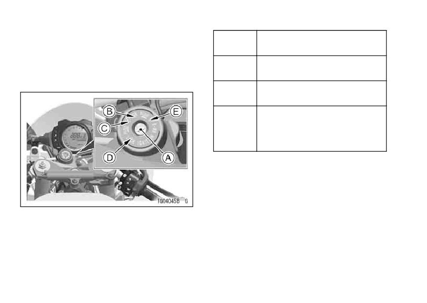
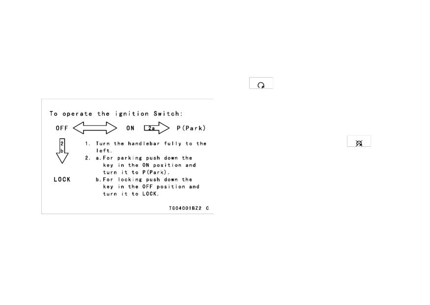
Ignition Switch/Steering Lock
Engine off. All electrical
OFF
This is a four-position, key-operated
circuits off.
switch. The key can be removed from
Engine on. All electrical
the switch when it is in the OFF, LOCK,
ON
equipment can be used.
or P (Park) position.
Steering locked. Engine off.
LOCK
All electrical circuits off.
Steering locked. Engine off.
Tail and license plate lights on.
P (Park)
All other electrical circuits cut
off.
NOTE
ż
The tail, city and license plate lights
are on whenever the ignition key is
in the ON position. One headlight
A. Ignition Switch/Steering Lock
goes on when the starter button is
B. ON position
released after starting the engine. To
C. OFF position
D. LOCK position
avoid battery discharge, always start
E. P (Park) position
GENERAL INFORMATION 45
the engine immediately after turning
Right Handlebar Switches
the ignition key to “ON”.
Engine Stop Switch:
żIf you leave the P (Park) position on
In addition to the ignition switch,
for a long time (one hour), the battery
the engine stop switch must be in
may become totally discharged.
the
position for the motorcycle to
operate.
The engine stop switch is for emer-
gency use. If some emergency re-
quires stopping the engine, move the
engine stop switch to the
position.
NOTE
żAlthough the engine stop switch
stops the engine, it does not turn off
all the electrical circuits. Ordinarily,
the ignition switch should be used to
stop the engine.
46 GENERAL INFORMATION
Starter Button:
The starter button operates the elec-
tric starter when the transmission is in
neutral.
Refer to the Starting the Engine sec-
tion of the “How to Ride the Motorcycle”
chapter for starting instructions.
START/STOP Switch (Stop Watch):
Refer to the Digital Meter section of
this chapter for stop watch instructions.
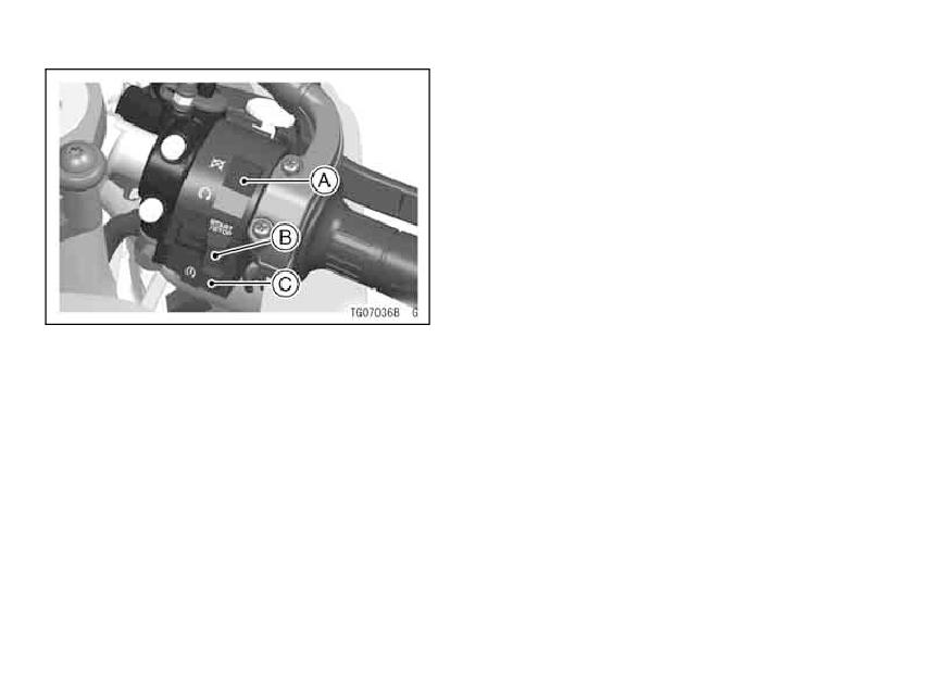
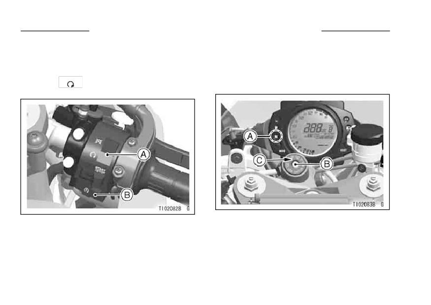
A. Engine Stop Switch
B. Start/Stop Switch (Stop Watch)
C. Starter Button
GENERAL INFORMATION 47
Left Handlebar Switches
Dimmer Switch:
High or low beam can be selected
with the dimmer switch. When the
headlight is on high beam (
), the
high beam indicator light is lit.
High beam
(
)
Low beam
(
)
NOTE
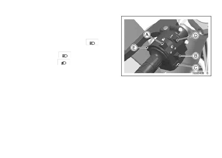
A. Dimmer Switch
żWhen the headlight is on high beam,
B. Turn Signal Switch
both headlights are lit. When the
C. Horn Button
headlight is on low beam, only one
D. Lap Button
headlight is lit.
E. Passing Button
48 GENERAL INFORMATION
Turn Signal Switch:
Brake Lever Adjuster
When the turn signal switch is turned
There is an adjuster on the brake
lever. The adjuster has 6 positions so
to the left (
) or right (
), the
that the released lever position can be
corresponding turn signals flash on and
adjusted to suit the operator’s hands.
off.
Push the lever forward and turn the ad-
To stop flashing, push the switch in.
juster to align the number with the mark
Horn Button:
on the lever holder. The distance from
When the horn button is pushed, the
the grip to the released lever is min-
horn sounds.
imum at Number 6 and maximum at
Number 1.
Passing Button:
When the passing button is pushed,
the headlight high beam (passing
beam) comes on to signal the driver of
the vehicle ahead that you are about to
pass him. The passing light shuts off
as soon as the button is released.
LAP Button:
Refer to the Digital Meter section of
the this chapter for stop watch instruc-
tions.
GENERAL INFORMATION 49
Fuel Tank Cap
To open the fuel tank cap, pull up the
key hole cover. Insert the ignition key
into the fuel tank cap and turn the key
to the right.
To close the cap, push it down into
place with the key inserted. The key
can be removed by turning it to the left
to the original position.
NOTE
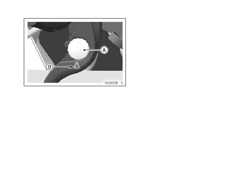
A. Adjuster
żThe fuel tank cap cannot be closed
B. Mark
without the key inserted, and the key
cannot be removed unless the cap is
locked properly.
żDo not push on the key to close the
cap, or the cap cannot be locked.
50 GENERAL INFORMATION
Fuel Tank
The following octane rating gasoline
is recommended in the fuel tank. Avoid
filling the tank in the rain or where
heavy dust is blowing so that the fuel
does not get contaminated.
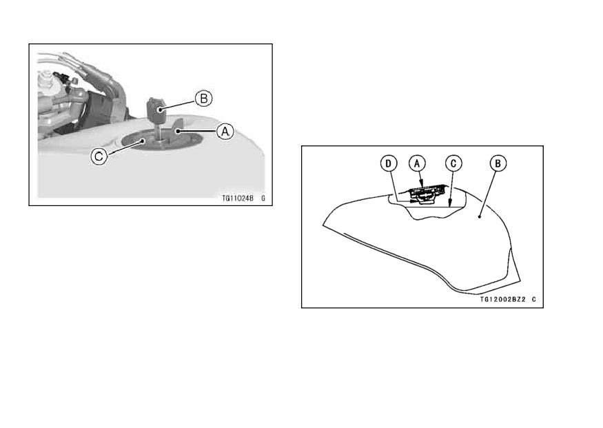
A. Key Hole Cover
B. Ignition Key
C. Fuel Tank Cap
A. Tank Cap
B. Fuel Tank
C. Top Level
D. Filler Neck
GENERAL INFORMATION 51
WARNING
Fuel Requirement:
Your Kawasaki engine is designed to
Gasoline is extremely flammable
use only unleaded gasoline with a min-
and can be explosive under cer-
imum octane rating of RON 95.
tain conditions. Turn the igni-
tion key to “OFF”. Do not smoke.
CAUTION
Make sure the area is well ven-
Do not use leaded gasoline, as
tilated and free from any source
this will destroy the catalytic
of flame or sparks; this includes
converter.
(For further infor-
any appliance with a pilot light.
mation, refer to the “Catalytic
Never fill the tank so the fuel
Converter” section in the “How
level rises into the filler neck. If
to Ride the Motorcycle” chap-
the tank is overfilled, heat may
ter.)
cause the fuel to expand and
overflow through the vents in
the tank cap.
After refueling, make sure the
fuel tank cap is closed securely.
If gasoline is spilled on the fuel
tank, wipe it off immediately.
52 GENERAL INFORMATION
Octane Rating
Side Stand
The octane rating of a gasoline is a
The motorcycle is equipped with a
measure of its resistance to detona-
side stand.
tion or “knocking”. The term commonly
used to describe a gasoline’s octane
rating is the Research Octane Number
(RON). Always use a gasoline with an
octane rating equal to, or higher than,
RON 95.
NOTE
żIf “knocking” or “pinging” occurs, use
a different brand of gasoline or higher
octane rating.
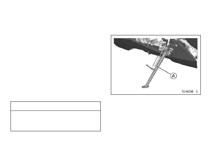
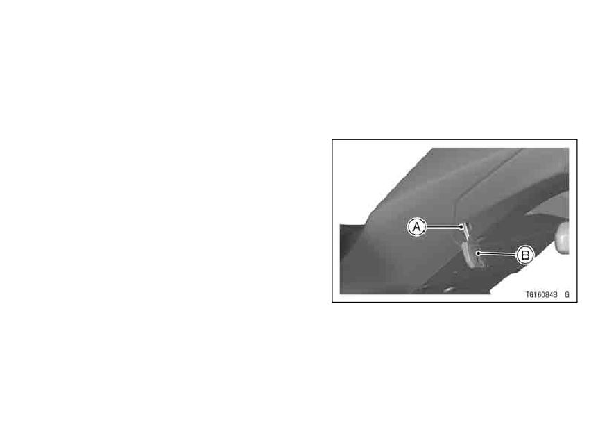
A. Side Stand
CAUTION
NOTE
Use minimum of 95 octane gaso-
żWhen using the side stand, turn the
line only to prevent severe en-
handlebar to the left.
gine damage.
Whenever the side stand is used,
make it a practice to kick the stand fully
up before sitting on the motorcycle.
GENERAL INFORMATION 53
NOTE
Seat Lock
żThe motorcycle is equipped with a
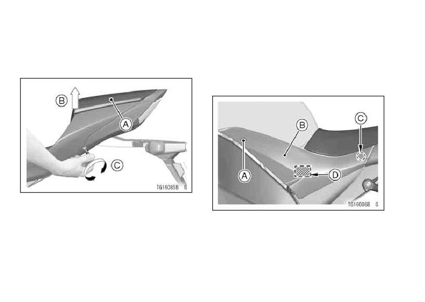
Passenger’s Seat Removal
side stand switch. This switch is de-
Remove the passenger’s seat by in-
signed so that the engine does not
serting the ignition key into the seat
start if the transmission is in gear and
lock, and turning it clockwise.
the side stand is down.
A. Seat Lock
B. Ignition Key
54 GENERAL INFORMATION
NOTE
Rider’s Seat Removal
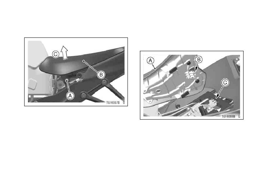
żWhen removing the passenger’s
• Remove the bolt.
seat, pull it up while turning the key.
• Remove the side cover by pulling out
it to detach the projection, and hook
-and-loop fastener.
A. Passenger’s Seat
B. Pull up
C. Turn the Key
A. Screw
B. Side Cover
C. Projection
D. Hook-and-Loop Fastener
GENERAL INFORMATION 55
Rider’s Seat -
• Remove the bolt and pull off the seat
to the up and front.
• Place the tab on the rear of the rider’s
seat into the slot in the frame and
tighten the bolt.
A. Bolt
B. Rider’s Seat
C. Pull Up and Front
A. Rider’s Seat
B. Tab
Seat Installation
C. Slot
Install the rider’s and passenger’s
seats in the reverse order of removal.

56 GENERAL INFORMATION
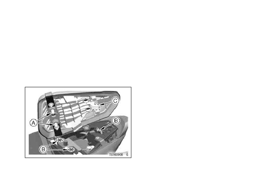
• Install the side cover and tighten the
bolt.
NOTE
żWhen installing the side cover, insert
the up of the cover into the under
of the rider’s seat as shown in the
figure.
żInsert the projection into the hole,
and attach the hook-and-loop fas-
tener of the side cover to one of the
A. Cover
fuel tank.
B. Projection
C. Hole
D. Hook-and-Loop Fastener
E. Up of Cover
F. Under of Rider’s Seat
GENERAL INFORMATION 57
Passenger’s Seat -
• Pull up the front and rear ends of
the passenger’s and rider’s seats to
• Insert the tab on the rear of the pas-
senger’s seat into the slot in the
make sure they are securely locked.
frame.
• Insert the left and right projections at
the front of the passenger’s seat into
the left and right slots on the frame.
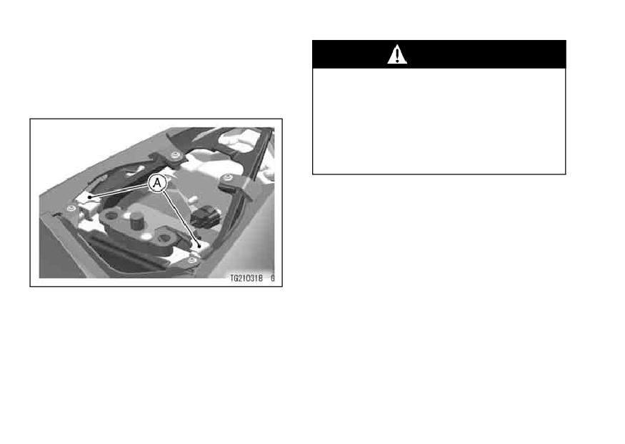
• Push down the front part of the pas-
senger’s seat until the lock clicks.
A. Projections
B. Slots
C. Tab
58 GENERAL INFORMATION
Helmet Hooks
WARNING
Helmets can be secured to the mo-
Do not ride the motorcycle with
torcycle using the helmet hooks located
helmets attached to the hooks.
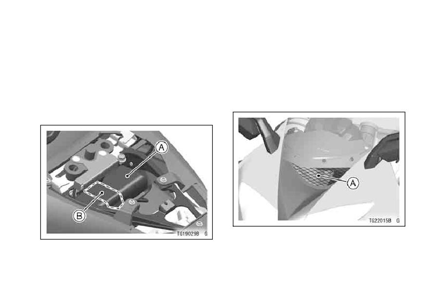
under the passenger’s seat.
The helmets could cause an ac-
cident by distracting the opera-
tor or interfering with normal ve-
hicle operation.
A. Helmet Hooks
GENERAL INFORMATION 59
Tool Kit
Air Cleaner Intake
The tool kit is located under the pas-
The air cleaner intake allows air to
senger’s seat.
enter the fuel system. Never allow any-
The kit contains tools that can be
thing to restrict the flow of air into the
helpful in making roadside repairs,
air cleaner. A restricted air cleaner will
adjustments, and some maintenance
reduce performance and increase ex-
procedures explained in this manual.
haust emissions.
Keep the tool kit in the original place.
A. Air Cleaner Intake
A. Tool Kit
B. Band
60 BREAK-IN
BREAK-IN
The first 1 600 km (1 000 mi) that the motorcycle is ridden is designated as the
break-in period. If the motorcycle is not used carefully during this period, you may
very well end up with a “broken down” instead of a “broken in” motorcycle after a
few thousand kilometers.
The following rules should be observed during the break-in period.
• The table shows maximum recommended engine speed during the break-in pe-
riod.
Distance traveled
Maximum engine speed
0 ∼ 800 km (0 ∼ 500 mi)
4 000 r/min (rpm)
800 ∼ 1 600 km (500 ∼ 1 000 mi)
6 000 r/min (rpm)
• Do not start moving or race the engine immediately after starting it, even if the
engine is already warm. Run the engine for two or three minutes at idle speed to
give the oil a chance to work up into all the engine parts.
• Do not race the engine while the transmission is in neutral.
BREAK-IN 61
WARNING
New tires are slippery and may cause loss of control and injury.
A break-in period of 160 km (100 miles) is necessary to establish normal
tire traction. During break-in, avoid sudden and maximum braking and
acceleration, and hard cornering.
In addition to the above, at 1 000 km (600 mi) it is extremely important that the
owner have the initial maintenance service performed by an authorized Kawasaki
dealer.
62 HOW TO RIDE THE MOTORCYCLE
HOW TO RIDE THE MOTORCYCLE
Starting the Engine
• Turn the ignition key to “ON”.
• Check that the engine stop switch is
• Make sure the transmission is in neu-
in the
position.
tral.
A. Neutral Indicator Light
A. Engine Stop Switch
B. Ignition Switch
B. Starter Button
C. ON position
HOW TO RIDE THE MOTORCYCLE 63
NOTE
CAUTION
żThe motorcycle is equipped with a
Do not operate the starter con-
vehicle-down sensor, which causes
tinuously for more than 5 sec-
the engine to stop automatically and
onds, or the starter will overheat
the fuel injection warning symbol to
and the battery power will drop
flash when the motorcycle falls down
temporarily. Wait 15 seconds
and the starter button pushed in. Af-
between each operation of the
ter righting the motorcycle, first turn
starter to let it cool and the bat-
the ignition key to “OFF” and then
tery power recover.
back to “ON” for a few seconds be-
fore starting the engine.
• After the meter operation check,
leaving the throttle completely
closed, push the starter button.

64 HOW TO RIDE THE MOTORCYCLE
NOTE
CAUTION
żThe motorcycle is equipped with a
Do not let the engine idle longer
starter lockout switch. This switch is
than five minutes, or engine
designed so that the engine does not
overheating and damage may
start if the transmission is in gear and
occur.
the side stand is down. However, the
engine can be started if the clutch
lever is pulled and the side stand is
fully up.
A. Clutch Lever
B. Starter Lockout Switch
HOW TO RIDE THE MOTORCYCLE 65
Jump Starting
WARNING
If your motorcycle battery is “run
Battery acid generates hydro-
down”, it should be removed and
gen gas which is flammable and
charged. If this is not practical, a 12
explosive under certain con-
volt booster battery and jumper cables
ditions. It is present within a
may be used to start the engine.
battery at all times, even in a
discharged condition. Keep all
flames and sparks (cigarettes)
away from the battery. Wear eye
protection when working with a
battery. In the event of battery
acid contact with skin, eyes, or
clothing, wash the affected ar-
eas immediately with water for at
least five minutes. Seek medical
attention.
Connecting Jumper Cables
• Remove the rider’s and passenger’s
seats.
• Make sure the ignition key is turned
to “OFF”.
66 HOW TO RIDE THE MOTORCYCLE
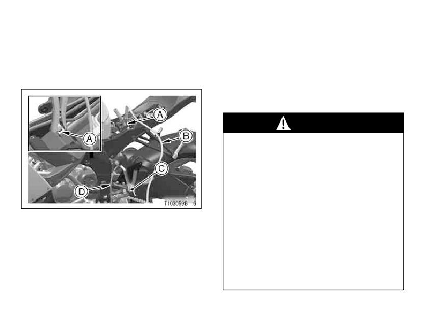
• Connect a jumper cable from the
• Connect another jumper cable from
positive (+) terminal of the booster
the negative
(-) terminal of the
battery to the positive (+) terminal of
booster battery to your motorcy-
the motorcycle battery.
cle footpeg or other unpained metal
surface. Do not use the negative (-)
terminal of the battery.
WARNING
Do not make this last connec-
tion at the fuel system or battery.
Take care that you do not touch
the positive and negative cables
together, and do not lean over
the battery when making this last
connection. Do not jump start a
A. Motorcycle Battery Positive (+) Terminal
frozen battery. It could explode.
B. From Booster Battery Positive (+) Terminal
C. Footpeg
Do not reverse polarity by con-
D. From Booster Battery Negative (-)
necting positive (+) to negative
Terminal
(-), or a battery explosion and
serious damage to the electrical
system may occur.
HOW TO RIDE THE MOTORCYCLE 67
Moving Off
• Follow the standard engine starting
procedure.
• Check that the side stand is up.
• Pull in the clutch lever.
CAUTION
• Shift into 1st gear.
• Open the throttle a little, and start to
Do not operate the starter con-
let out the clutch lever very slowly.
tinuously for more than 5 sec-
• As the clutch starts to engage, open
onds or the starter will overheat
the throttle a little more, giving the en-
and the battery power will drop
gine just enough fuel to keep it from
temporarily. Wait 15 seconds
stalling.
between each operation of the
starter to let it cool and the bat-
tery power recover.
• After the engine has started, discon-
nect the jumper cables. Disconnect
the negative (-) cable from the mo-
torcycle first.
• Reinstall the parts removed.
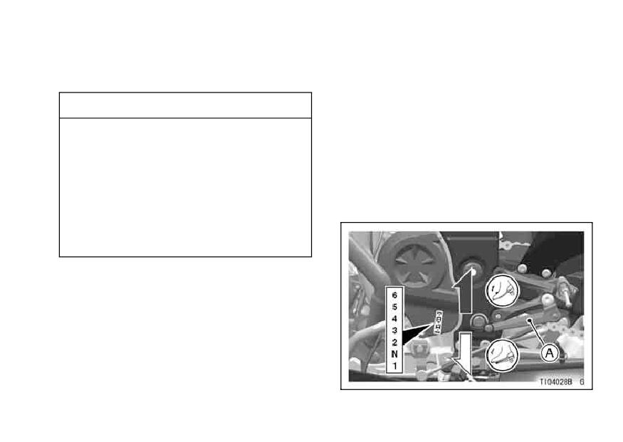
A. Shift Pedal
68 HOW TO RIDE THE MOTORCYCLE
NOTE
Shifting Gears
żThe motorcycle is equipped with a
• Close the throttle while pulling in the
side stand switch. This switch is de-
clutch lever.
signed so that the engine does not
• Shift into the next higher or lower
gear.
start if the transmission is in gear and
the side stand is down.
żWhen the headlight is on high beam,
WARNING
two headlight beams are lit, and on
When shifting down to a lower
low beam, the one side of the head-
gear, do not shift at such a high
light is lit.
speed that the engine r/min
(rpm) jumps excessively. Not
only can this cause engine dam-
age, but the rear wheel may skid
and cause an accident. Down-
shifting should be done below
5 000 r/min (rpm) for each gear.
• Open the throttle part way, while re-
leasing the clutch lever.
HOW TO RIDE THE MOTORCYCLE 69
NOTE
Braking
żThe transmission is equipped with a
• Close the throttle completely, leav-
positive neutral finder. When the mo-
ing the clutch engaged (except when
torcycle is standing still, the transmis-
shifting gears) so that the engine will
help slow down the motorcycle.
sion cannot be shifted past neutral
from 1st gear. To use the positive
• Shift down one gear at a time so that
you are in 1st gear when you come
neutral finder, shift down to 1st gear,
to a complete stop.
then lift up on the shift pedal while
standing still. The transmission will
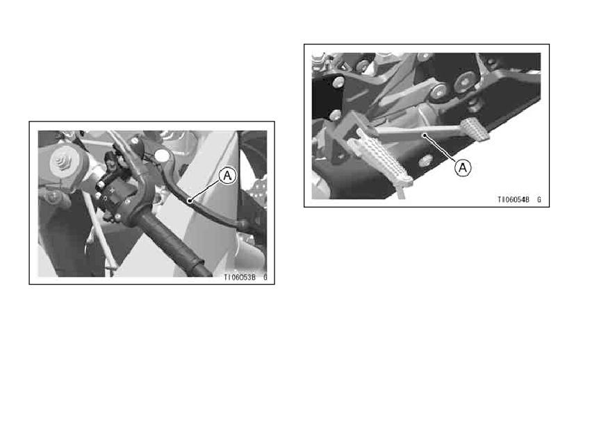
• When stopping, always apply both
brakes at the same time. Normally
shift only into neutral.
the front brake should be applied a lit-
tle more than the rear. Shift down or
fully disengage the clutch as neces-
sary to keep the engine from stalling.
• Never lock the brakes, or it will cause
the tires to skid. When turning a cor-
ner, it is better not to brake at all. Re-
duce your speed before you get into
the corner.
70 HOW TO RIDE THE MOTORCYCLE
• For emergency braking, disregard
downshifting, and concentrate on
applying the brakes as hard as pos-
sible without skidding.
A. Rear Brake Pedal
A. Front Brake Lever
HOW TO RIDE THE MOTORCYCLE 71
Stopping the Engine
Stopping the Motorcycle in an
Emergency
• Close the throttle completely.
Your Kawasaki Motorcycle has been
• Shift the transmission into neutral.
designed and manufactured to pro-
• Turn the ignition key to “OFF”.
vide you optimum safety and conve-
• Support the motorcycle on a firm,
level surface with the side stand.
nience. However, in order to fully ben-
efit from Kawasaki’s safety engineering
• Lock the steering.
and craftsmanship, it is essential that
NOTE
you, the owner and operator, properly
maintain your motorcycle and become
żThe motorcycle is equipped with a
vehicle-down sensor, which causes
thoroughly familiar with its operation.
the engine to stop automatically and
Improper maintenance can create a
the fuel injection warning symbol to
dangerous situation known as throt-
flash when the motorcycle falls down
tle failure. Two of the most common
and the starter button pushed in. Af-
causes of throttle failure are:
ter righting the motorcycle, first turn
1. An improperly serviced or clogged
the ignition key to “OFF” and then
air cleaner may allow dirt and dust
back to “ON” for a few seconds be-
to enter the throttle body and stick
fore starting the engine.
the throttle open.
72 HOW TO RIDE THE MOTORCYCLE
2. During removal of the air cleaner,
Parking
dirt is allowed to enter and jam the
• Shift the transmission into neutral
fuel injection system.
and turn the ignition key to “OFF”.
In an emergency situation such as
• Support the motorcycle on a firm,
level surface with the side stand.
throttle failure, your vehicle may be
stopped by applying the brakes and
disengaging the clutch.
Once this
CAUTION
stopping procedure is initiated, the en-
Do not park on a soft or steeply
gine stop switch may be used to stop
inclined surface, or the motorcy-
the engine. If the engine stop switch is
cle may fall over.
used, turn off the ignition switch after
stopping the motorcycle.
• If parking inside a garage or other
structure, be sure it is well ventilated
and the motorcycle is not close to
any source of flame or sparks; this
includes any appliance with a pilot
light.
HOW TO RIDE THE MOTORCYCLE 73
WARNING
NOTE
The muffler and exhaust pipe
żWhen stopping near traffic at night,
you can leave the taillight on for
are very hot while the engine is
greater visibility by turning the igni-
running and just after the engine
tion key to the P (park) position.
stops. This can ignite a fire, re-
sulting in property damage or
żDo not leave the ignition switch at P
position too long, or the battery will
severe personal injury.
discharge.
Do not idle or park your vehi-
cle in an area where flammable
materials such as grasses or dry
leaves may contact with muffler
or exhaust pipe.
WARNING
Gasoline is extremely flammable
and can be explosive under cer-
tain conditions.
• Lock the steering to help prevent
theft.
74 HOW TO RIDE THE MOTORCYCLE
Catalytic Converter
WARNING
This motorcycle is equipped with a
The muffler and exhaust pipe
catalytic converter in the exhaust sys-
are very hot while the engine is
tem. Palladium, platinum and rhodium
running and just after the engine
in the converter react with carbon
stops. This can ignite a fire, re-
monoxide and hydrocarbons to convert
sulting in property damage or
them into carbon dioxide and water re-
severe personal injury.
sulting in much cleaner exhaust gases
Do not idle or park your vehi-
to be discharged into the atmosphere.
cle in an area where flammable
For proper operation of the catalytic
materials such as grasses or dry
converter, the following cautions must
leaves may contact with muffler
be observed.
or exhaust pipe.
HOW TO RIDE THE MOTORCYCLE 75
• Use only unleaded gasoline. Never
use leaded gasoline. Leaded gaso-
line significantly reduces the capabil-
ity of the catalytic converter.
• Do not coast the vehicle with the igni-
tion switch and/or engine stop switch
off. Do not attempt to start the en-
gine by rolling the vehicle if the bat-
tery is discharged. Do not operate
the vehicle with the engine or any
one cylinder misfiring. Under these
conditions unburned air/fuel mixture
flowing out of engine excessively ac-
celerates reaction in the converter al-
lowing the converter to overheat and
become damaged when the engine
is hot, or reduces converter perfor-
mance when the engine is cold.
76 SAFE OPERATION
SAFE OPERATION
Safe Riding Technique
The points given below are applicable for everyday motorcycle use and should
be carefully observed for safe and effective vehicle operation.
For safety, eye protection and a
Before changing lanes, look over
helmet are strongly recommended.
your shoulder to make sure the way
You should be aware of and verify
is clear. Do not rely solely on the
the applicable safety regulations in
rear view mirror; you may misjudge
force prior to riding your motorcy-
a vehicle’s distance and speed, or
cle. Gloves and suitable footwear
you may not see it at all.
should also be used for added pro-
tection.
When going up steep slopes, shift
to a lower gear so that there is plenty
A motorcycle does not provide
of power to spare rather than over-
the impact protection of an auto-
loading the engine.
mobile, so defensive riding in addi-
tion to wearing protective apparel
When applying the brakes, use
is extremely important. Do not let
both the front and rear brakes. Ap-
protective apparel give you a false
plying only one brake for sudden
sense of security.
SAFE OPERATION 77
braking may cause the motorcycle
When riding in wet conditions or
to skid and lose control.
on loose roadway surfaces, the abil-
ity to maneuver will be reduced. All
When going down long slopes,
of your actions should be smooth
control vehicle speed by closing
under these conditions. Sudden ac-
the throttle. Use the front and rear
celeration, braking or turning may
brakes for auxiliary braking.
cause loss of control.
In wet conditions, rely more on the
On rough roads, exercise caution,
throttle to control vehicle speed and
slow down, and grip the fuel tank
less on the front and rear brakes.
with the knees for better stability.
The throttle should also be used ju-
diciously to avoid skidding the rear
When quick acceleration is neces-
wheel from too rapid acceleration or
sary as in passing, shift to a lower
deceleration.
gear to obtain the necessary power.
Riding at the proper rate of speed
Do not downshift at too high an
and avoiding unnecessarily fast ac-
r/min (rpm) to avoid damage to the
celeration are important not only for
engine from overrevving.
safety and low fuel consumption but
also for long vehicle life and quieter
Avoiding unnecessary weaving is
operation.
important to the safety of both the
rider and other motorists.
78 SAFE OPERATION
Daily Safety Checks
Check the following items each day before you ride. The time required is minimal,
and habitual performance of these checks will help ensure you a safe, reliable ride.
If any irregularities are found during these checks, refer to the Maintenance and
Adjustment chapter or see your dealer for the action required to return the motor-
cycle to a safe operating condition.
WARNING
Failure to perform these checks every day before you ride may result in
serious damage or a severe accident.
Fuel
Adequate supply in tank, no leaks.
Engine oil
Oil level between level lines.
Tires
Air pressure (when cold):
Front
250 kPa (2.50 kgf/cm², 36 psi)
Rear
290 kPa (2.90 kgf/cm², 42 psi)
Install the air valve cap.
Drive chain
Slack 30 ∼ 40 mm (1.2 ∼ 1.6 in.).
Lubricate when chain is dry.
Nuts, bolts, fasteners .. Check that steering and suspension components, axles,
and all controls are properly tightened or fastened.
SAFE OPERATION 79
Steering
Action smooth but not loose from lock to lock.
No binding of control cables.
Steering Damper Unit: No oil leakage.
Brakes
Brake pad wear: Lining thickness more than 1 mm (0.04
in.) left.
No brake fluid leakage.
Throttle
Throttle grip play 2 ∼ 3 mm (0.08 ∼ 0.12 in.).
Clutch
Clutch lever play 2 ∼ 3 mm (0.08 ∼ 0.12 in.).
Clutch lever operates smoothly.
Coolant
No coolant leakage.
Coolant level between level lines (when engine is cold).
Electrical equipment ...
All lights (Headlight, Tail/Brake Lights, Turn Signal Lights,
Warning/Indicator Lights) and horn work.
Engine stop switch
Stops engine.
Side stand
Return to its fully up position by spring tension.
Return spring not weak or not damaged.
Refer to the “Daily Safety Checks” caution label attached to the back of left side
cover.
80 SAFE OPERATION
Additional Considerations for High Speed Operation
Brakes: The importance of the brakes, especially during high speed operation,
cannot be overemphasized. Check to see that they are correctly adjusted and func-
tioning properly.
Steering: Looseness in the steering can cause loss of control. Check to see that
the handlebar turns freely but has no play.
Tires: High speed operation is hard on tires, and good tires are crucial for riding
safety. Examine their overall condition, inflate them to the proper pressure, and
check the wheel balance.
Fuel: Have sufficient fuel for the high fuel consumption during high speed oper-
ation.
Engine Oil: To avoid engine seizure and resulting loss of control, make sure that
the oil level is at the upper level line.
Coolant: To avoid overheating, check that the coolant level is at the upper level
line.
Electrical Equipment: Make sure that the headlight, tail/brake light, turn signals,
horn, etc., all work properly.
Miscellaneous: Make sure that all nuts and bolts are tight and that all safety
related parts are in good condition.
SAFE OPERATION 81
WARNING
Handling characteristics of a motorcycle at high speeds may vary from
those you are familiar with at legal highway speeds. Do not attempt high
speed operation unless you have received sufficient training and have the
required skills.
82 MAINTENANCE AND ADJUSTMENT
MAINTENANCE AND ADJUSTMENT
The maintenance and adjustments outlined in this chapter must be carried out in
accordance with the Periodic Maintenance Chart to keep the motorcycle in good
running condition. The initial maintenance is vitally important and must not be
neglected.
With a basic knowledge of mechanics and the proper use of tools, you should be
able to carry out many of the maintenance items described in this chapter. If you
lack proper experience or doubt your ability, all adjustments, maintenance, and
repair work should be completed by a qualified technician.
Please note that Kawasaki cannot assume any responsibility for damage result-
ing from incorrect or improper adjustment done by the owner.
MAINTENANCE AND ADJUSTMENT 83
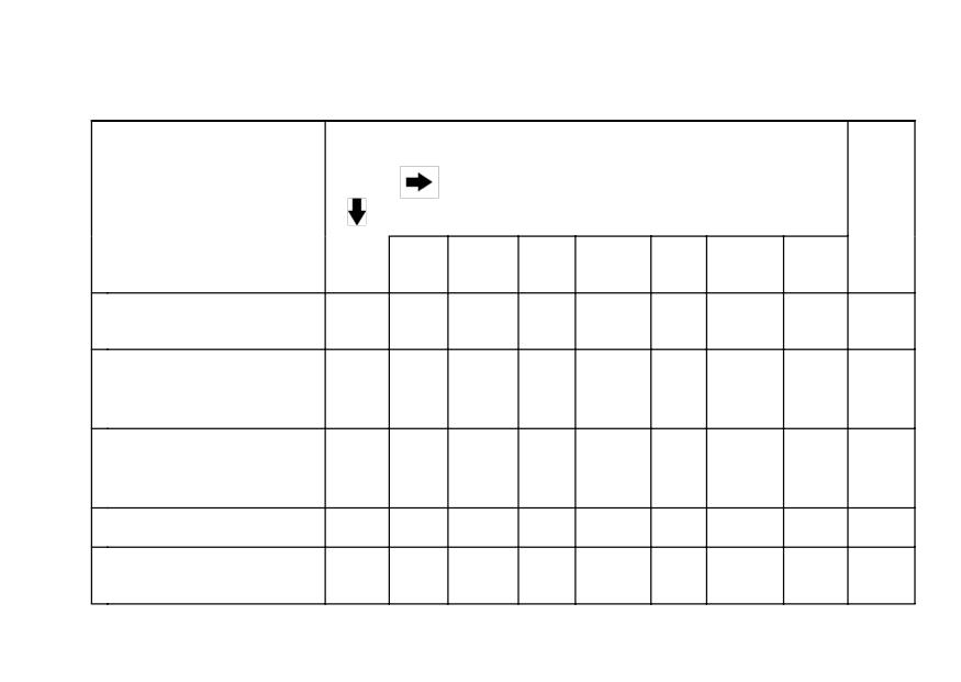
Periodic Maintenance Chart
1. Periodic Inspection (Engine Related Items)
Frequency
Whichever
comes
*Odometer Reading
first
km × 1 000 (mile × 1 000)
See
Page
Operation (Engine
Ev-
1
6
12
18
24
30
36
Items)
ery
(0.6)
(3.75)
(7.5)
(11.25)
(15)
(18.75)
(22.5)
Valve clearance -
K
105
inspect
•
Throttle control system
(play, smooth return,
year
112
•
•
•
•
no drag) - inspect
Engine vacuum
Ksynchronization -
115
•
•
•
inspect
Idle speed - inspect
115
•
•
•
•
Fuel leak (fuel hose
K
year
-
and pipe) - inspect
•
•
•
•
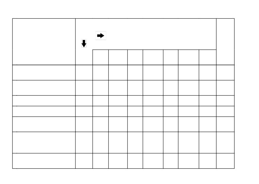
84 MAINTENANCE AND ADJUSTMENT
Frequency
Whichever
comes
*Odometer Reading
first
km × 1 000 (mile × 1 000)
See
Page
Operation (Engine
Ev-
1
6
12
18
24
30
36
Items)
ery
(0.6)
(3.75)
(7.5)
(11.25)
(15)
(18.75)
(22.5)
Fuel hoses damage -
K
year
-
inspect
•
•
•
•
Fuel hoses installation
K
year
-
condition - inspect
•
•
•
•
Coolant level - inspect
100
•
•
•
•
Coolant leak - inspect
year
98
•
•
•
•
Radiator hose damage
year
98
- inspect
•
•
•
•
Radiator hoses
installation condition -
year
98
•
•
•
•
inspect
Air suction system
K
105
damage - inspect
•
•
•
MAINTENANCE AND ADJUSTMENT 85
2. Periodic Inspection (Chassis Related Items)
Frequency
Whichever
comes
*Odometer Reading
first
km × 1 000 (mile × 1 000)
See
Page
Operation (Chassis
Ev-
1
6
12
18
24
30
36
Items)
ery
(0.6)
(3.75)
(7.5)
(11.25)
(15)
(18.75)
(22.5)
Clutch and drive
train:
Clutch operation
(play, engagement,
117
disengagement) -
•
•
•
•
inspect
Drive chain
lubrication condition -
every 600 km (400 mile)
128
inspect #
Drive chain slack -
every 1 000 km (600 mile)
119
inspect #
Drive chain wear -
123
inspect #
•
•
•
86 MAINTENANCE AND ADJUSTMENT
Frequency
Whichever
comes
*Odometer Reading
first
km × 1 000 (mile × 1 000)
See
Page
Operation (Chassis
Ev-
1
6
12
18
24
30
36
Items)
ery
(0.6)
(3.75)
(7.5)
(11.25)
(15)
(18.75)
(22.5)
Drive chain guide
K
-
wear - inspect
•
•
•
Wheels and tires:
Tire air pressure -
year
146
inspect
•
•
•
Wheels/tires damage
147
- inspect
•
•
•
Tire tread wear,
abnormal wear -
147
•
•
•
inspect
Wheel bearings
K
year
-
damage - inspect
•
•
•
Brake system:
MAINTENANCE AND ADJUSTMENT 87
Frequency
Whichever
comes
*Odometer Reading
first
km × 1 000 (mile × 1 000)
See
Page
Operation (Chassis
Ev-
1
6
12
18
24
30
36
Items)
ery
(0.6)
(3.75)
(7.5)
(11.25)
(15)
(18.75)
(22.5)
Brake fluid leak -
year
130
inspect
•
•
•
•
•
•
•
Brake hoses damage
year
130
- inspect
•
•
•
•
•
•
•
Brake pad wear -
129
inspect #
•
•
•
•
•
•
Brake hose
installation condition
year
130
•
•
•
•
•
•
•
- inspect
Brake fluid level -
6
130
inspect
month
•
•
•
•
•
•
•
Brake operation
(effectiveness, play,
year
132
•
•
•
•
•
•
•
drag) - inspect
88 MAINTENANCE AND ADJUSTMENT
Frequency
Whichever
comes
*Odometer Reading
first
km × 1 000 (mile × 1 000)
See
Page
Operation (Chassis
Ev-
1
6
12
18
24
30
36
Items)
ery
(0.6)
(3.75)
(7.5)
(11.25)
(15)
(18.75)
(22.5)
Brake light switch
132
operation - inspect
•
•
•
•
•
•
•
Suspensions:
Front forks/rear
shock absorber
136/
operation (damping
•
•
•
141
and smooth stroke) -
inspect
Front forks/rear
136/
shock absorber oil
year
•
•
•
141
leak - inspect
Uni-trak rocker arm
K
-
operation - inspect
•
•
•
Uni-trak tie rods
K
-
operation - inspect
•
•
•
MAINTENANCE AND ADJUSTMENT 89
Frequency
Whichever
comes
*Odometer Reading
first
km × 1 000 (mile × 1 000)
See
Page
Operation (Chassis
Ev-
1
6
12
18
24
30
36
Items)
ery
(0.6)
(3.75)
(7.5)
(11.25)
(15)
(18.75)
(22.5)
Steering system:
Steering play -
K
year
-
inspect
•
•
•
•
Steering stem
2
K
-
bearings - lubricate
years
•
Steering damper oil
135
leak - inspect
•
•
•
•
•
•
90 MAINTENANCE AND ADJUSTMENT
Frequency
Whichever
comes
*Odometer Reading
first
km × 1 000 (mile × 1 000)
See
Page
Operation
1
6
12
18
24
30
36
Every
(Chassis Items)
(0.6)
(3.75)
(7.5)
(11.25)
(15)
(18.75)
(22.5)
Electrical system:
Lights and switches
year
-
operation - inspect
•
•
•
Headlight aiming -
year
156
inspect
•
•
•
Side stand switch
year
-
operation - inspect
•
•
•
Engine stop switch
year
-
operation - inspect
•
•
•
Chassis:
Chassis parts -
K
year
-
lubricate
•
•
•
Bolts and nuts
K
-
tightness - inspect
•
•
•
•
MAINTENANCE AND ADJUSTMENT 91
3. Periodic Replacement
Frequency
Whichever
comes
*Odometer Reading
first
km × 1 000 (mile × 1 000)
See
Page
Change/Replace-
1
12
24
36
48
Every
ment Items
(0.6)
(7.5)
(15)
(22.5)
(30)
Air cleaner element #
every 18 000 km (11 250 mile)
107
K Engine oil #
year
95
•
•
•
•
•
KOil filter
year
95
•
•
•
•
•
K Fuel hoses
4 years
-
•
KCoolant
3 years
103
•
Radiator hoses and
K
3 years
-
O-rings
•
KBrake hoses
4 years
-
•
Brake fluid (front and
K
2 years
132
rear)
•
•
92 MAINTENANCE AND ADJUSTMENT
Frequency
Whichever
comes
*Odometer Reading
first
km × 1 000 (mile × 1 000)
See
Page
Change/Replace-
1
12
24
36
48
Every
ment Items
(0.6)
(7.5)
(15)
(22.5)
(30)
Rubber parts of
Kmaster cylinder and
4 years
-
•
caliper
KSpark plug
104
•
•
•
•
K : Should be serviced by an authorized Kawasaki dealer.
* : For higher odometer readings, repeat at the frequency interval established here.
# : Service more frequently when operating in severe conditions: dusty, wet, muddy,
high speed, or frequent starting/stopping.
MAINTENANCE AND ADJUSTMENT 93
Engine Oil
Oil Level Inspection
In order for the engine, transmission,
• If the oil has just been changed, start
and clutch to function properly, main-
the engine and run it for several min-
tain the engine oil at the proper level,
utes at idle speed. This fills the oil
and change the oil and replace the oil
filter with oil. Stop the engine, then
filter in accordance with the Periodic
wait several minutes until the oil set-
Maintenance Chart. Not only do dirt
tles.
and metal particles collect in the oil, but
the oil itself loses its lubricative quality
CAUTION
if used too long.
Racing the engine before the oil
reaches every part can cause en-
WARNING
gine seizure.
Motorcycle operation with insuf-
ficient, deteriorated, or contami-
• If the motorcycle has just been used,
nated engine oil will cause accel-
wait several minutes for all the oil to
erated wear and may result in en-
drain down.
gine or transmission seizure, ac-
cident, and injury.
94 MAINTENANCE AND ADJUSTMENT
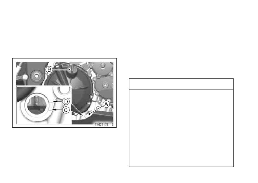
• Check the engine oil level through
• If the oil level is too high, remove the
the oil level gauge. With the motor-
excess oil through the oil filler open-
cycle held level, the oil level should
ing using a syringe or some other
come up between the upper and
suitable device.
lower level lines next to the gauge.
• If the oil level is too low, add the oil
to reach the correct level. Use the
same type and brand of oil that is
already in the engine.
CAUTION
If the engine oil gets extremely
low or if the oil pump does not
function properly or oil pas-
sages are clogged, the warning
light in the meter instrument and
oil pressure warning symbol in
A. Oil Level Inspection Window
the digital meter will flash. If
B. Oil Filler Cap
C. Lower Level Line
they flash on while the engine
D. Upper Level Line
running above the idle speed,
stop the engine immediately and
find the cause.
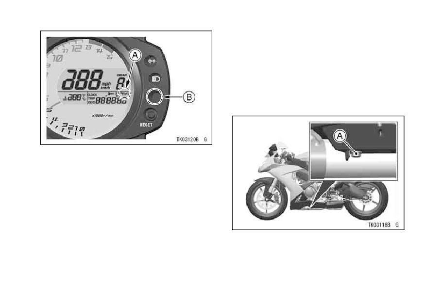
MAINTENANCE AND ADJUSTMENT 95
Oil and/or Oil Filter Change
•To change the engine oil and replace
and oil filter must be removed. The
oil change and oil filter replacement
should be done by an authorized
Kawasaki dealer.
A. Oil Pressure Warning Symbol
B. Warning Light
A. Engine Oil Drain Plug
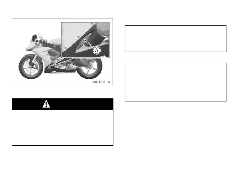
96 MAINTENANCE AND ADJUSTMENT
Tightening Torque
Engine Oil Drain Plug:
30 N·m (3.1 kgf·m, 22 ft·lb)
Cartridge:
17 N·m (1.7 kgf·m, 13 ft·lb)
Recommended Engine Oil
Type:
API SE, SF or SG
API SH, SJ or SL with JASO MA, MA1
or MA2
A. Oil Filter Cartridge
Viscosity:
SAE10W-40
WARNING
NOTE
Motor oil is a toxic substance.
Dispose of used oil properly.
żDo not add any chemical additive to
Contact your local authorities
the oil. Oils fulfilling the above re-
for approved disposal methods
quirements are fully formulated and
or possible recycling.
provide adequate lubrication for both
the engine and the clutch.
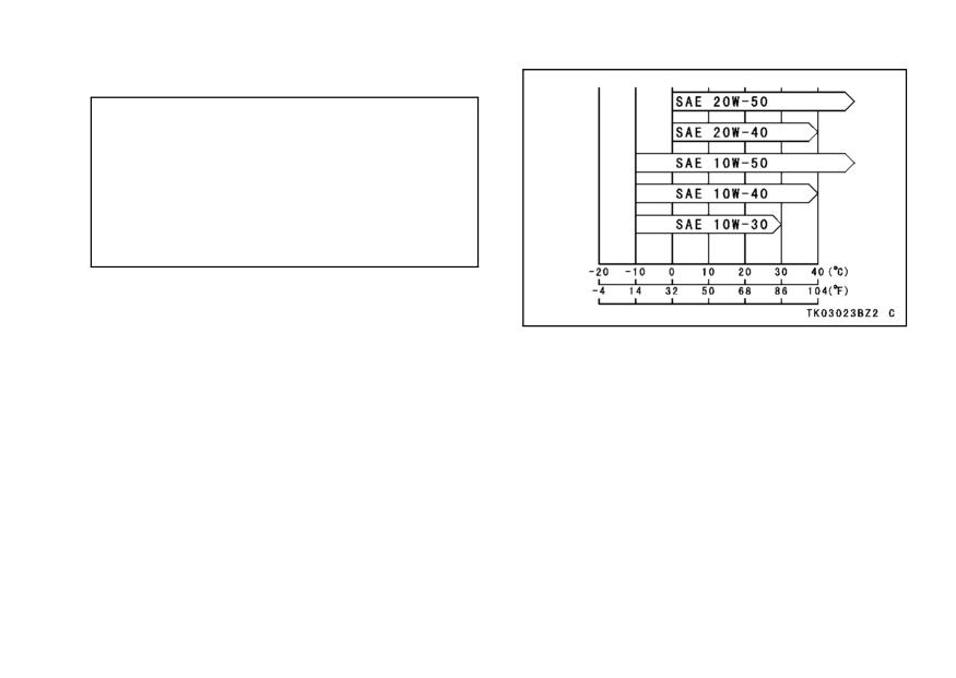
MAINTENANCE AND ADJUSTMENT 97
Engine Oil Capacity
Capacity:
3.2 L (3.4 US qt)
[when filter is not removed]
3.7 L (3.9 US qt)
[when filter is removed]
4.0 L (4.2 US qt)
[when engine is completely dry]
Although 10W-40 engine oil is the
recommended oil for most condi-
tions, the oil viscosity may need to
be changed to accommodate atmo-
spheric conditions in your riding area.
98 MAINTENANCE AND ADJUSTMENT
Cooling System
CAUTION
Radiator and Cooling Fan -
Using high-pressure water, as
Check the radiator fins for obstruc-
from a car wash facility, could
tion by insects or mud.
Clean off
damage the radiator fins and im-
any obstructions with a stream of
pair the radiator’s effectiveness.
low-pressure water.
Do not obstruct or deflect air-
flow through the radiator by
WARNING
installing unauthorized acces-
sories in front of the radiator or
Keep your hands and clothing
behind the cooling fan. Inter-
away from the cooling fan blades
ference with the radiator airflow
at all times.
can lead to overheating and con-
sequent engine damage.
Radiator Hoses -
Check the radiator hoses for leakage,
cracks or deterioration, and connec-
tions for leakage, or looseness each
day before riding the motorcycle, and
in accordance with the Periodic Main-
tenance Chart.
MAINTENANCE AND ADJUSTMENT 99
Coolant -
a period of time, the cooling system
Coolant absorbs excessive heat from
accumulates rust and scale in the wa-
the engine and transfers it to the air
ter jacket and radiator. This will clog
at the radiator. If the coolant level be-
up the coolant passages, and con-
comes low, the engine overheats and
siderably reduce the efficiency of the
may suffer severe damage. Check the
cooling system.
coolant level each day before riding the
motorcycle, also in accordance with the
WARNING
periodic maintenance chart and replen-
Use coolant containing corro-
ish coolant if the level is low. Change
sion inhibitors made specifically
the coolant in accordance with the Pe-
for aluminum engines and ra-
riodic Maintenance Chart.
diators in accordance with the
Information for Coolant
instructions of the manufacturer.
To protect the cooling system (con-
Chemicals are harmful to the hu-
sisting of the aluminum engine and
man body.
radiator) from rust and corrosion, the
use of corrosion and rust inhibitor
Soft or distilled water must be used
chemicals in the coolant is essential. If
with the antifreeze (see below for an-
coolant containing corrosion and rust
tifreeze) in the cooling system.
inhibitor chemicals are not used, over
100 MAINTENANCE AND ADJUSTMENT
CAUTION
CAUTION
If hard water is used in the sys-
Permanent types of antifreeze on
tem, it causes scale accumula-
the market have anti-corrosion
tion in the water passages, and
and anti-rust properties. When it
considerably reduces the effi-
is diluted excessively, it loses its
ciency of the cooling system.
anti-corrosion property. Dilute a
permanent type of antifreeze in
If the lowest ambient temperature en-
accordance with the instructions
countered falls below the freezing point
of the manufacturer.
of water, use permanent antifreeze in
the coolant to protect the cooling sys-
NOTE
tem against engine and radiator freeze
żA permanent type of antifreeze is in-
-up, as well as from rust and corrosion.
stalled in the cooling system when
Use a permanent type of antifreeze
shipped. It is colored green and con-
(soft water and ethylene glycol plus cor-
tains ethylene glycol. It is mixed at
rosion and rust inhibitor chemicals for
50% and has the freezing point of
aluminum engines and radiators) in the
-35 °C (-31 °F).
cooling system. On the mixture ratio
of coolant, choose the suitable one re-
Coolant Level Inspection
ferring to the relation between freezing
point and strength directed on the con-
• Situate the motorcycle so that it is
perpendicular to the ground.
tainer.
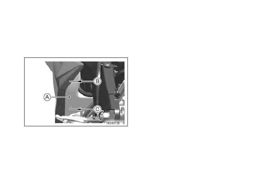
MAINTENANCE AND ADJUSTMENT 101
NOTE
• Check the coolant level through the
coolant level gauge on the reserve
żCheck the level when the engine is
tank located to the left of the engine.
cold (room or atmospheric tempera-
The coolant level should be between
ture).
the F (Full) and L (Low) level lines.
If the amount of coolant is insuffi-
•
cient, add coolant into the reserve
tank.
•Removethedcapofrom theureserve
filler opening to the F (Full) level line.
A. Reserve Tank
B. F (Full) Level Line
C. L (Low) Level Line
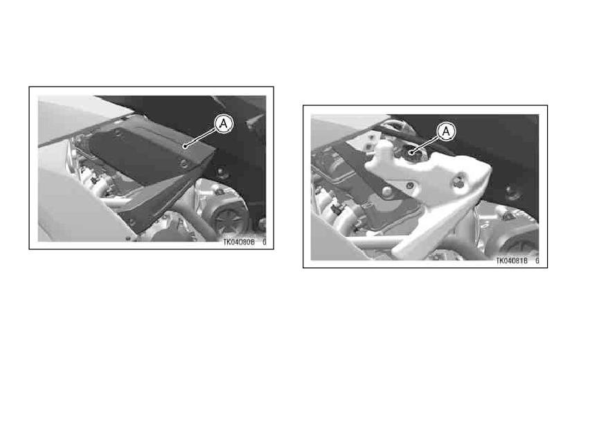
102 MAINTENANCE AND ADJUSTMENT
Coolant Filing
• Remove the cap from the reserve
tank and add coolant through the
• Remove the front left side cover.
filler opening to the F (Full) level line.
A. Front Left Side Cover
A. Reserve Tank Cap
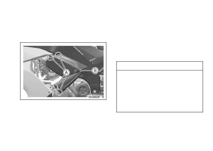
MAINTENANCE AND ADJUSTMENT 103
NOTE
• When installing the front left side
cover, insert the tab of the top and
żIn an emergency you can add wa-
under on the cover into the each hole
ter alone to the coolant reserve tank,
of the fairing.
however it must be returned to the
correct mixture ratio by the addition
of antifreeze concentrate as soon as
possible.
CAUTION
If coolant must be added of-
ten, or the reserve tank com-
pletely runs dry, there is proba-
bly leakage in the system. Have
the cooling system inspected
A. Tab
by your authorized Kawasaki
B. Front Left Side Cover
dealer.
Coolant Change
Have the coolant changed by an au-
thorized Kawasaki dealer.
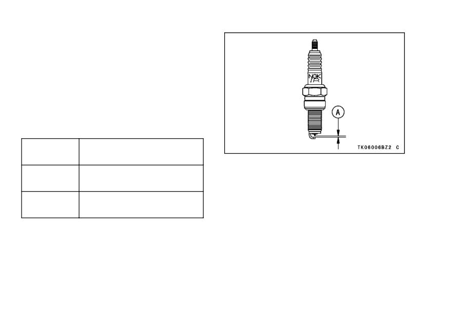
104 MAINTENANCE AND ADJUSTMENT
Spark Plugs
The standard spark plug is shown in
the table. The spark plugs should be
replaced in accordance with the Peri-
odic Maintenance Chart.
Spark plug removal should be done
by an authorized Kawasaki dealer.
Spark Plug
Standard
NGK CR9EIA-9
Plug:
A. 0.8 ∼ 0.9 mm (0.032 ∼ 0.035 in.)
0.8 ∼ 0.9 mm
Plug Gap:
(0.032 ∼ 0.036 in.)
Tightening
13 N·m (1.3 kgf·m, 10 ft·lb)
Torque:
MAINTENANCE AND ADJUSTMENT 105
Valve Clearance
Kawasaki Clean Air System
Valve and valve seat wear decreases
The Kawasaki Clean Air System
valve clearance, upsetting valve timing.
(KCA) is a secondary air suction sys-
tem that helps the exhaust gases to
CAUTION
burn more completely. When the spent
fuel charge is released into the ex-
If valve clearance is left un-
haust system, it is still hot enough to
adjusted, wear will eventually
burn. The KCA System allows extra
cause the valves to remain
air into the exhaust system so that the
partly open; which lowers per-
spent fuel charge can continue to burn.
formance, burns the valves and
This continued burning action tends to
valve seats, and may cause seri-
burn up a great deal of the normally
ous engine damage.
unburned gases, as well as chang-
Valve clearance for each valve
ing a significant portion of the carbon
should be checked and adjusted in
monoxide into carbon dioxide.
accordance with the Periodic Mainte-
nance Chart.
Inspection and adjustment should
be done by an authorized Kawasaki
dealer.
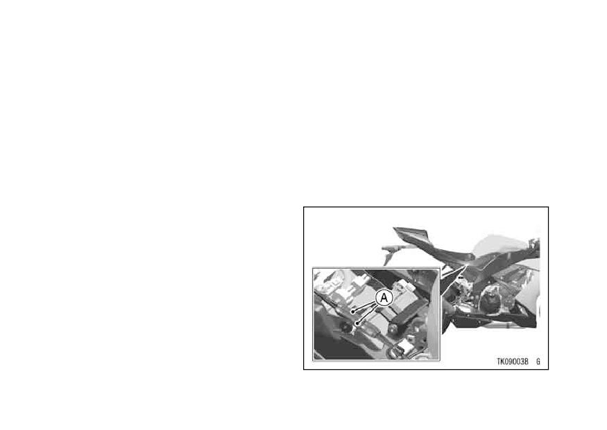
106 MAINTENANCE AND ADJUSTMENT
Air Suction Valves -
Exhaust Device
The air suction valve is essentially a
This motorcycle is equipped with a
check valve which allows fresh air to
exhaust device system. This system
flow only from the air cleaner into the
controls the valve in the exhaust pipe
exhaust port. Any air that has passed
and produces stable engine power at
the air suction valve is prevented from
low and middle engine speed. This ex-
returning. Inspect the air suction valves
haust device is controlled by the ECU,
in accordance with the Periodic Main-
and adjustment or maintenance should
tenance Chart. Also, inspect the air
be done by an authorized Kawasaki
suction valves whenever stable idling
dealer.
cannot be obtained, engine power is
greatly reduced, or there are abnormal
engine noises.
Air suction valve removal and inspec-
tion should be done by an authorized
Kawasaki dealer.
A. Exhaust Device Cables
MAINTENANCE AND ADJUSTMENT 107
CAUTION
Air Cleaner
A clogged air cleaner restricts the en-
Do not adjust the exhaust device
gine’s air intake, increasing fuel con-
system by yourself. The mal-
sumption, reducing engine power, and
adjustment will cause the poor
causing spark plug fouling.
engine performance and engine
This motorcycle’s air cleaner element
damage.
consists of a wet paper filter, which can-
not be cleaned.
The air cleaner element must be re-
placed in accordance with the Periodic
Maintenance Chart. In dusty, rainy, or
muddy conditions, the air cleaner el-
ement should be serviced more fre-
quently than the recommended inter-
val.
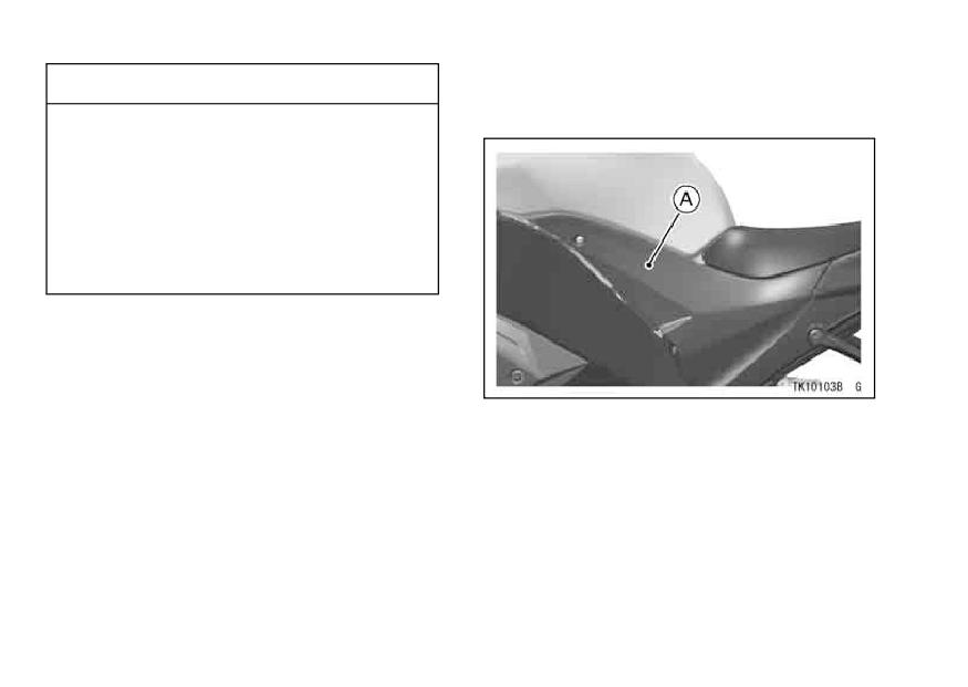
108 MAINTENANCE AND ADJUSTMENT
CAUTION
• Remove the left and right side cov-
ers.
Use only the recommended air
cleaner element (Kawasaki part
number 11013-0026 or equiva-
lent type). Using the another
air cleaner element will wear the
engine prematurely or lower the
engine performance.
A. Left Side Cover
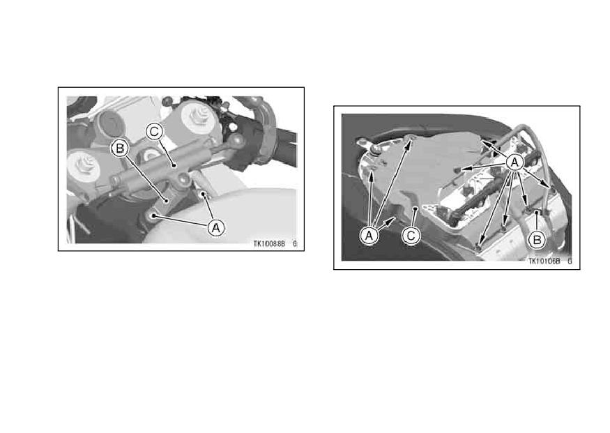
MAINTENANCE AND ADJUSTMENT 109
• Remove the rider’s seat.
• Raise the front of the fuel tank.
• Remove the bracket bolt.
• Remove the air cleaner housing
cover screws with clamp and cover.
A. Bracket Bolts
B. Bracket
A. Screws
C. Steering Damper Unit
B. Clamp
C. Air Cleaner Housing Cover
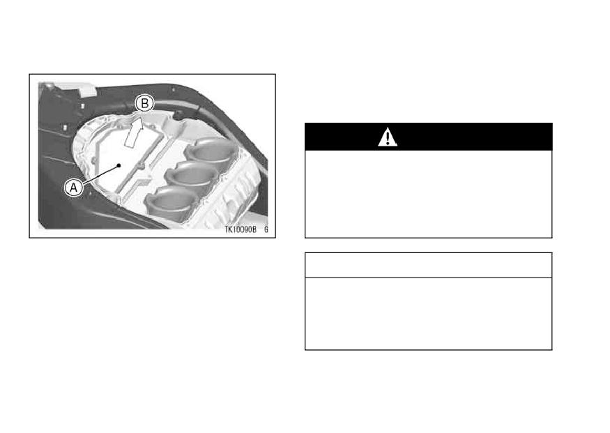
110 MAINTENANCE AND ADJUSTMENT
• Pull up the air cleaner element.
• Put a clean, lint-free towel over the
air cleaner element duct to keep dirt
or other foreign material from enter-
ing.
WARNING
If dirt or dust is allowed to pass
through into the fuel injection
system, the throttle may become
stuck, possibly causing an acci-
dent.
A. Element
B. Pull Up
CAUTION
If dirt gets through into the en-
gine, excessive engine wear and
possibly engine damage will oc-
cur.
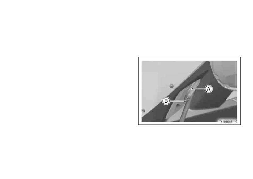
MAINTENANCE AND ADJUSTMENT 111
NOTE
Oil Draining
żElement and fuel tank installation is
• Inspect the transparent hose located
on the left lower side of the engine to
performed in the reverse order of re-
see if any oil or water has run down
moval.
from the air cleaner housing.
A. Transparent Hose
B. Plug
112 MAINTENANCE AND ADJUSTMENT
Throttle Control System
• If there is any oil in the hose, remove
the plug and drain the oil.
Check the throttle grip play each day
before riding the motorcycle, and in
accordance with the Periodic Mainte-
WARNING
nance Chart, and adjust it if necessary.
Be sure to install the plug in the
Throttle Grip -
drain hose after draining. Oil on
The throttle grip controls the butterfly
tires will make them slippery and
valves in the throttle body. If the throt-
can cause an accident and in-
tle grip has excessive play due to either
jury.
cable stretch or maladjustment, it will
cause a delay in throttle response, es-
pecially at low engine speed. Also, the
throttle valve may not open fully at full
throttle. On the other hand, if the throt-
tle grip has not play, the throttle will be
hard to control, and the idle speed will
be erratic.
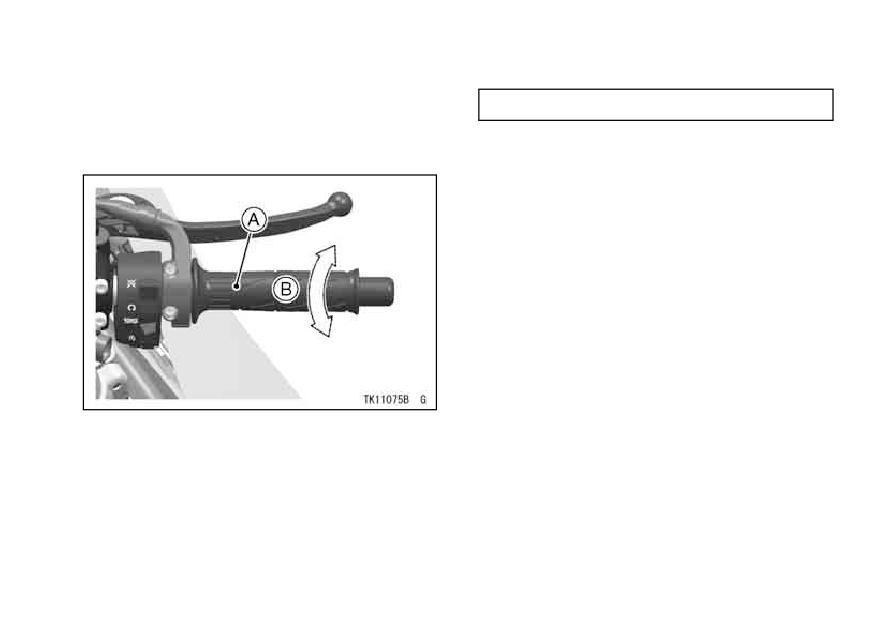
MAINTENANCE AND ADJUSTMENT 113
Inspection
Throttle Grip Play
• Check that the throttle grip play is
2 ∼ 3 mm (0.08 ∼ 0.12 in.)
correct by lightly turning the throttle
grip back and forth.
• If there is improper play, adjust it.
Adjustment
•Loosenthelocknutsaattherupperof
throttle cable adjusters in completely
so as to give the throttle grip plenty
of play.
•Turnroutilthedeceleratorncablead-
tle grip is completely closed. Tighten
the locknut.
A. Throttle Grip
• Turn out the accelerator cable ad-
B. Throttle Grip Play
juster until the throttle grip has the
proper play. Tighten the locknut.
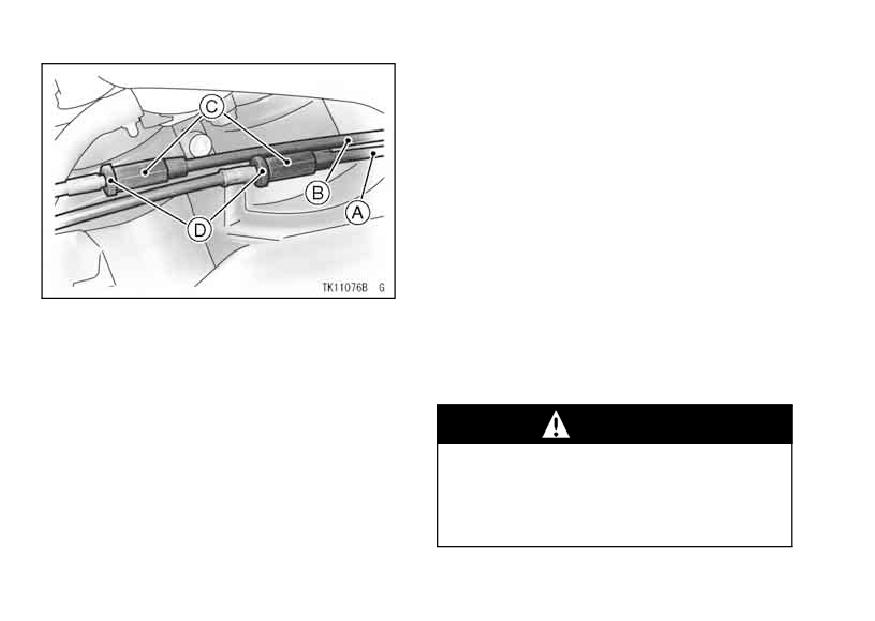
114 MAINTENANCE AND ADJUSTMENT
• If the throttle cables cannot be ad-
justed with the adjuster at the up-
per of the throttle cable, further ad-
justment of the throttle cables should
be done by an authorized Kawasaki
dealer.
•Withtheengineidling,turnthelhan-
movement changes the idle speed,
the throttle cables may be improp-
erly adjusted or in correctly routed,
A. Decelerator Cable
B. Accelerator Cable
or they may be damaged. Be sure
C. Adjuster
to correct any of these conditions be-
D. Locknuts
fore idling.
WARNING
Operation with improperly ad-
justed, incorrectly routed, or
damaged cables could result in
an unsafe riding condition.
MAINTENANCE AND ADJUSTMENT 115
Engine Vacuum Synchronization
Idle Speed
Engine vacuum synchronization
The idle speed adjustment should be
must be checked and adjusted period-
performed in accordance with the Pe-
ically in accordance with the Periodic
riodic Maintenance Chart or whenever
Maintenance Chart by an authorized
the idle speed is disturbed.
Kawasaki dealer.
Adjustment
NOTE
• Start the engine, and warm it up thor-
oughly.
żPoor engine vacuum synchronization
will cause unstable idling, sluggish
• Adjust the idle speed by turning the
idle adjusting screw.
throttle response, and reduce engine
power and performance.
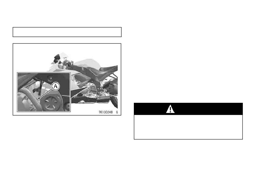
116 MAINTENANCE AND ADJUSTMENT
Idle Speed
• Open and close the throttle a few
times to make sure that the idle
1 050 ∼ 1 150 r/min (rpm)
speed does not change. Readjust if
necessary.
• With the engine idling, turn the han-
dlebar to each side. If handlebar
movement changes the idle speed,
the throttle cables may be improperly
adjusted or incorrectly routed, or they
may be damaged. Be sure to correct
any of these conditions before riding.
WARNING
A. Idle Adjusting Screw
Operation with damaged cables
could result in an unsafe riding
condition.
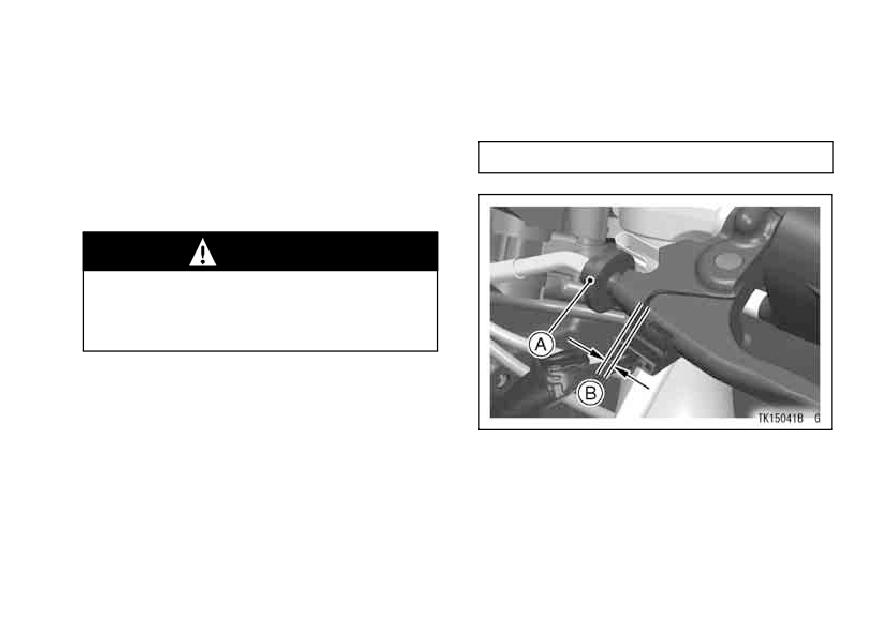
MAINTENANCE AND ADJUSTMENT 117
Clutch
• Check the clutch lever play as shown
Due to friction plate wear and clutch
in the figure.
cable stretch over a long period of use,
Clutch Lever Play
the clutch operation should be checked
2 ∼ 3 mm (0.08 ∼ 0.12 in.)
each day before riding the motorcycle,
and must be adjusted in accordance
with the Periodic Maintenance Chart.
WARNING
To avoid a serious burn, never
touch a hot engine or an exhaust
pipe during clutch adjustment.
Inspection
• Check that the clutch lever operates
properly and that the inner cable
A. Adjuster
slides smoothly. If there is any irreg-
B. Clutch Lever Play
ularity, have the clutch cable checked
If the play is incorrect, adjust the lever
by an authorized Kawasaki dealer.
play as follows.
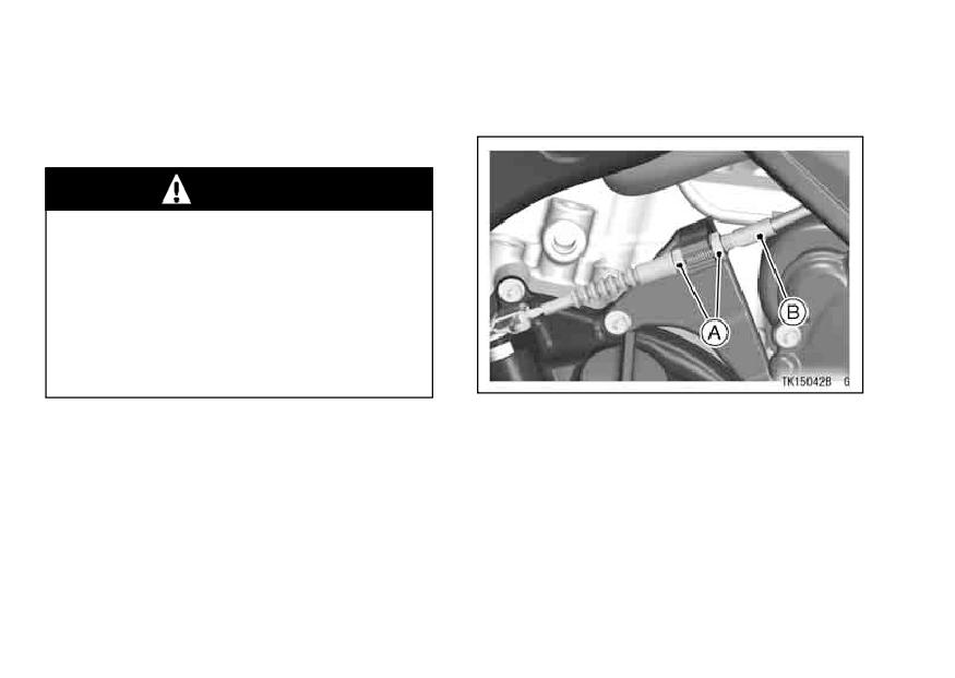
118 MAINTENANCE AND ADJUSTMENT
Adjustment
• If it cannot be done, use the nuts at
the lower end of the clutch cable.
• Turn the adjuster so that the clutch
lever will have the proper play.
WARNING
Be sure the upper end of the
clutch outer cable is fully seated
in its fitting, or it could slip into
place later, creating enough ca-
ble play to prevent clutch dis-
engagement, resulting in a haz-
ardous riding condition.
A. Nuts
B. Clutch Cable
NOTE
żAfter the adjustment is made, start
the engine and check that the clutch
does not slip and that it releases
properly.
żFor minor corrections, use the ad-
juster at the clutch lever.
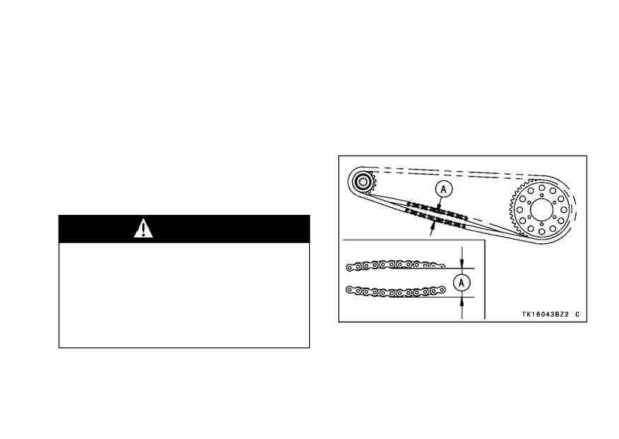
MAINTENANCE AND ADJUSTMENT 119
Drive Chain
• Rotate the rear wheel to find the po-
The drive chain slack and lubrica-
sition where the chain is tightest, and
tion must be checked each day be-
measure the maximum chain slack
fore riding the motorcycle, and in accor-
by pulling up and pushing down the
dance with the Periodic Maintenance
chain midway between the engine
Chart for safety and to prevent exces-
sprocket and rear wheel sprocket.
sive wear. If the chain becomes badly
worn or maladjusted - either too loose
or too tight - the chain could jump off
the sprockets or break.
WARNING
A chain that breaks or jumps off
the sprockets could snag on the
engine sprocket or lock the rear
wheel, severely damaging the
motorcycle and causing it to go
out of control.
A. Chain Slack
If the drive chain is too tight or too
•
Chain Slack Inspection
loose, adjust it so that the chain slack
will be within the standard value.
• Set the motorcycle up on its side
stand.
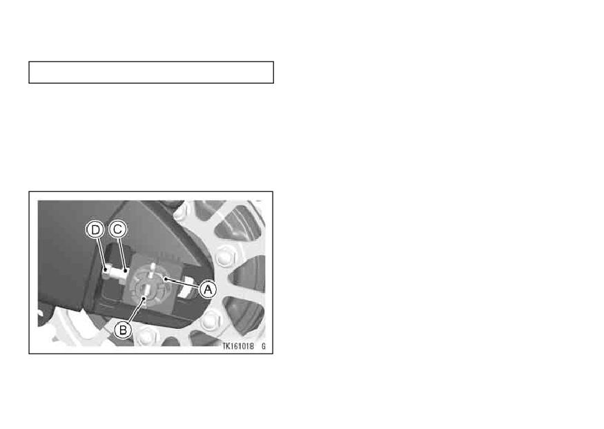
120 MAINTENANCE AND ADJUSTMENT
Drive Chain Slack
• If the chain is too loose, turn out the
left and right chain adjusters evenly.
Standard: 30 ∼ 40 mm (1.2 ∼ 1.6 in.)
If the chain is too tight, turn in the left
•
and right chain adjusters evenly.
Chain Slack Adjustment
• Turn out both chain adjusters evenly
• Loosen the left and right chain ad-
until the drive chain has the cor-
juster locknuts.
rect amount of slack. To keep the
• Remove the cotter pin, and loosen
chain and wheel properly aligned,
the axle nut.
the notch on the left wheel alignment
indicator should align with the same
swingarm mark that the right indica-
tor notch aligns with.
A. Axle Nut
B. Cotter Pin
C. Adjuster
D. Locknut
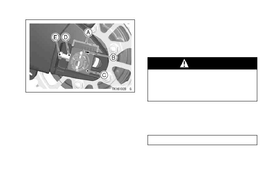
MAINTENANCE AND ADJUSTMENT 121
NOTE
ż
Wheel alignment can also be
checked using the straightedge or
string method.
WARNING
Misalignment of the wheel will
result in abnormal wear, and may
result in an unsafe riding condi-
A. Marks
tion.
B. Notch
C. Indicator
• Tighten both chain adjuster locknuts.
D. Adjuster
• Tighten the axle nut to the specified
E. Locknut
torque.
Tightening Torque
Axle Nut: 108 N·m (11.0 kgf·m, 79.7 ft·lb)
NOTE
żIf a torque wrench is not available,
this item should be serviced by a
Kawasaki dealer.
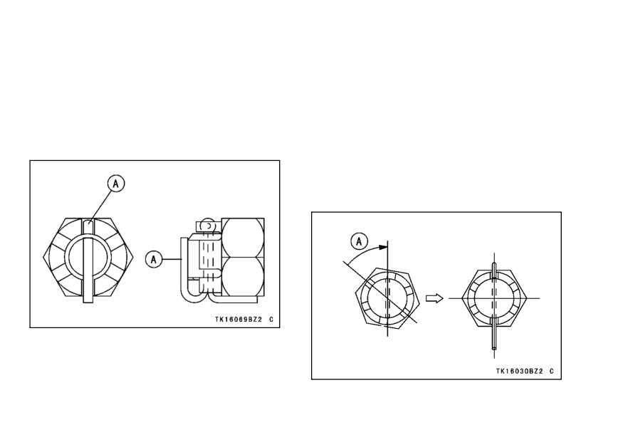
122 MAINTENANCE AND ADJUSTMENT
NOTE
• Rotate the wheel, measure the chain
slack again at the tightest position,
żWhen inserting the cotter pin, if the
and readjust if necessary.
slots in the nut do not align with
the cotter pin hole in the axle shaft,
• Install a new cotter pin through the
axle nut and axle, and spread its
tighten the nut clockwise up to the
ends.
next alignment.
żIt should be within 30 degree.
żLoosen once and tighten again when
the slot goes past the nearest hole.
A. Cotter Pin
A. Turn Clockwise
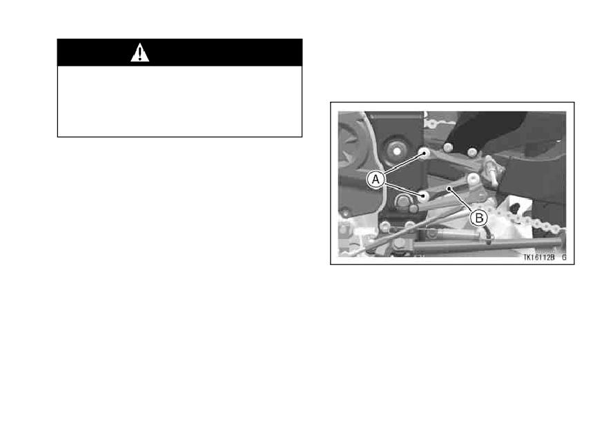
MAINTENANCE AND ADJUSTMENT 123
WARNING
Wear Inspection
If the axle nut is not securely
• Remove the front footpeg bracket
bolts.
tightened or the cotter pin is not
installed, an unsafe riding condi-
tion may result.
• Check the rear brake (see the Brakes
section).
A. Front Footpeg
B. Bolts
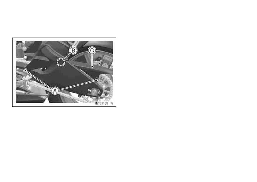
124 MAINTENANCE AND ADJUSTMENT
NOTE
• Remove the chain cover bolts and
quick rivet.
żThe chain cover uses the quick rivet.
The quick rivet can be removed by
pushing the central pin into the quick
rivets, and when installing it, pull the
central pin fully up first, and then
push into the central pin after insert-
ing them.
A. Bolts
B. Quick Rivet
C. Chain Cover
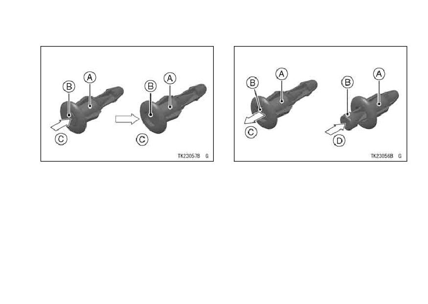
MAINTENANCE AND ADJUSTMENT 125
Quick Rivet Removal
Quick Rivet Removal
A. Quick Rivet
A. Quick Rivet
B. Center Pin
B. Center Pin
C. Push in.
C. Pull up fully.
D. Push in.
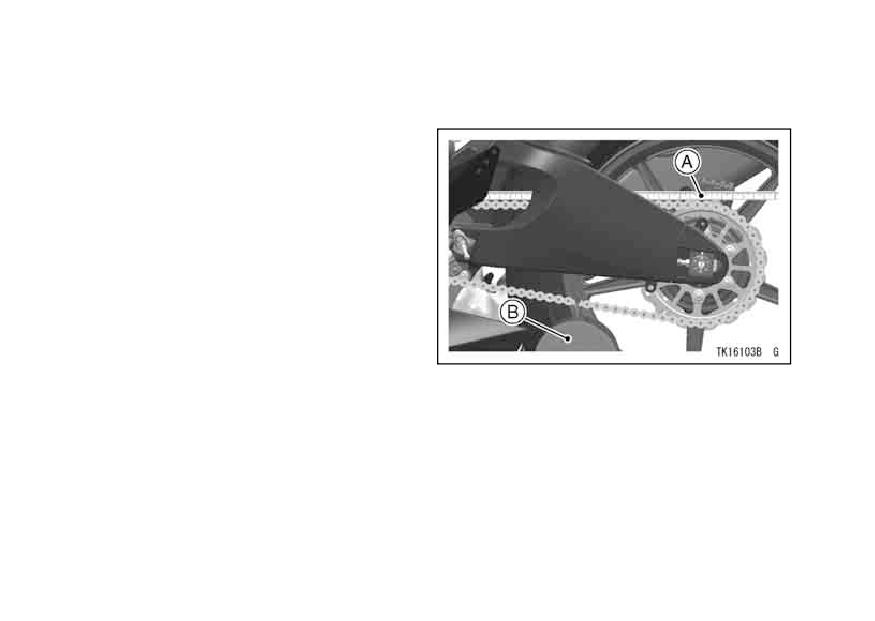
126 MAINTENANCE AND ADJUSTMENT
• Stretch the chain taut either by using
• If the length exceeds the service limit,
the chain adjusters, or by hanging a
the chain should be replaced.
10 kg (20 lb) weight on the chain.
• Measure the length of 20 links on
the straight part of the chain from pin
center of the 1st pin to pin center of
the 21st pin. Since the chain may
wear unevenly, take measurements
at several places.
A. Measure
B. Weight
MAINTENANCE AND ADJUSTMENT 127
Drive Chain 20-Link Length
WARNING
For safety, use only the standard
Service Limit: 323 mm (12.7 in.)
chain. It is an endless type and
should not be cut for installa-
NOTE
tion; have it installed by an au-
żInstall the chain cover and front foot-
thorized Kawasaki dealer.
peg bracket in the reverse order of
removal.
• Rotate the rear wheel to inspect the
drive chain for damaged rollers, and
żApply the nonpermanent locking
loose pins and links.
agent to the chain cover font side
bolt.
• Also inspect the sprockets for un-
evenly or excessively worn teeth,
Tightening Torque
and damaged teeth.
Front Footpeg Bracket Bolt: 25 N·m (2.5
kgf·m, 18 ft·lb)
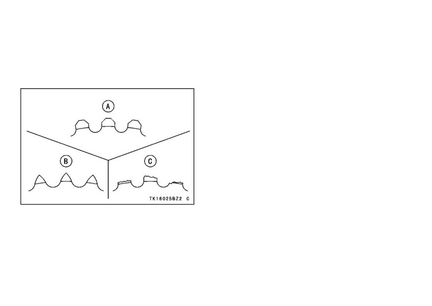
128 MAINTENANCE AND ADJUSTMENT
NOTE
Lubrication
Lubrication is also necessary after
żSprocket wear is exaggerated for il-
riding through rain or on wet roads, or
lustration. See Service Manual for
any time that the chain appears dry. A
wear limits.
heavy oil such as SAE 90 is preferred
to a lighter oil because it will stay on the
chain longer and provide better lubrica-
tion.
A. Good Teeth
B. Worn Teeth
C. Damaged Teeth
• If there is any irregularity, have the
drive chain and/or the sprockets re-
placed by an authorized Kawasaki
dealer.
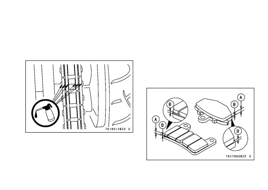
MAINTENANCE AND ADJUSTMENT 129
Brakes
• Apply oil to the sides of the rollers so
that it will penetrate to the rollers and
Brake Wear Inspection
bushings. Apply oil to the O-rings so
Inspect the brakes for wear. For each
that the O-rings will be coated with
front and rear disc brake caliper, if the
oil. Wipe off any excess oil.
thickness of either pad is less than
1 mm (0.04 in.), replace both pads
in the caliper as a set. Pad replace-
ment should be done by an authorized
Kawasaki dealer.
• If the chain is especially dirty, clean it
using diesel oil or kerosine and then
apply oil as described above.
A. Lining Thickness
B. 1 mm (0.04 in.)
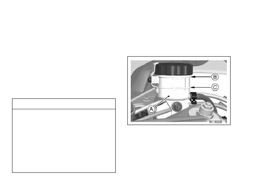
130 MAINTENANCE AND ADJUSTMENT
Disc Brake Fluid -
Fluid Level Inspection
In accordance with the Periodic Main-
• With the brake fluid reservoirs held
tenance Chart, inspect the brake fluid
horizontal, the brake fluid level must
level in both the front and rear brake
be kept between the upper and lower
fluid reservoirs and change the brake
level lines.
fluid. The brake fluid should also be
changed if it becomes contaminated
with dirt or water.
Fluid Requirement
Use heavy-duty brake fluid only from
a container marked DOT4.
CAUTION
Do not spill brake fluid onto any
painted surface.
Do not use fluid from a container
A. Front Brake Fluid Reservoir
that has been left open or that
B. Upper Level Line
has been unsealed for a long
C. Lower Level Line
time.
Check for fluid leakage around
the fittings.
Check brake hose for damage.
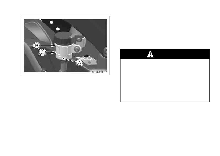
MAINTENANCE AND ADJUSTMENT 131
• If the fluid level in either reservoir is
lower than the lower level line, check
for fluid leaks in the brake lines, and
fill the reservoir to the upper level
line.
WARNING
Do not mix two brands of brake
fluid. Change the brake fluid in
the brake line completely if the
A. Rear Brake Fluid Reservoir
brake fluid must be refilled but
B. Upper Level Line
the type and brand of the brake
C. Lower Level Line
fluid that is already in the reser-
voir are unidentified.
NOTE
żWhen filling the brake fluid, remove
the cap by loosing the nut.
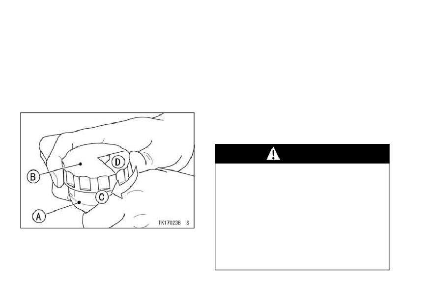
132 MAINTENANCE AND ADJUSTMENT
NOTE
Fluid Change
Have the brake fluid changed by an
żFirst, tighten until slight resistance is
authorized Kawasaki dealer.
felt indicating that the cap is seated
on the reservoir body; tighten the cap
Front and Rear Brakes -
an additional 1/6 turn while holding
Disc and disc pad wear is automat-
the brake fluid reservoir body.
ically compensated for and has no ef-
fect on the brake lever or pedal action.
So there are no parts that require ad-
justment on the front and rear brakes.
WARNING
If the brake lever or pedal feels
mushy when it is applied, there
might be air in the brake lines
or the brake may be defective.
Since it is dangerous to operate
the motorcycle under such con-
A. Reservoir
ditions, have the brake checked
B. Cap
immediately by an authorized
C. Clockwise
D. 1/6 turn
Kawasaki dealer.
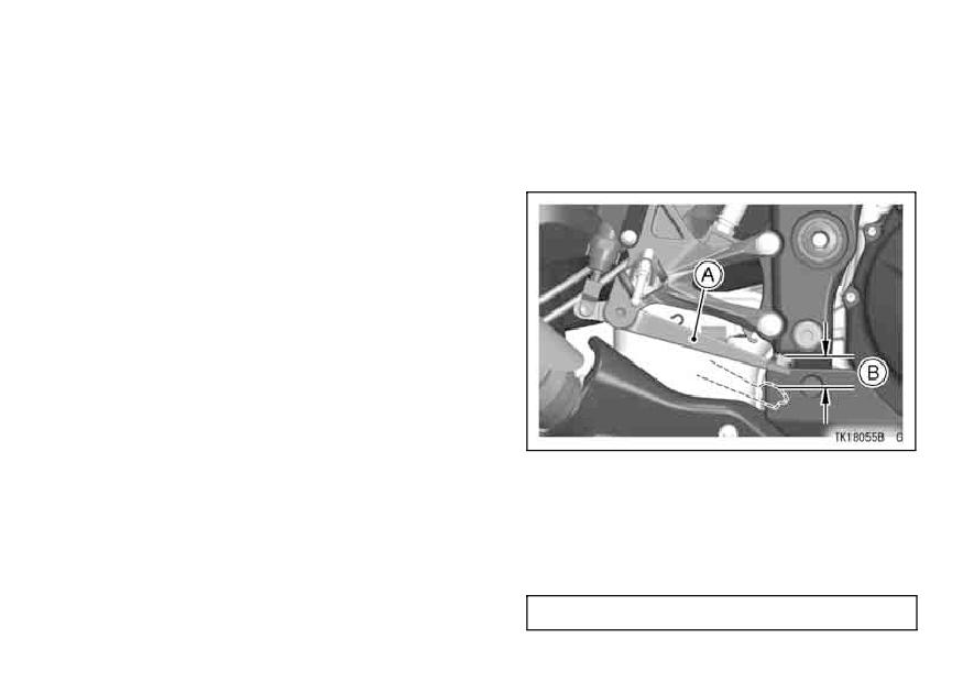
MAINTENANCE AND ADJUSTMENT 133
Brake Light Switches
• Check the operation of the rear brake
When either the front or rear brake is
light switch by depressing the brake
applied, the brake light goes on. The
pedal. The brake light should go on
front brake light switch requires no ad-
after the proper pedal travel.
justment, but the rear brake light switch
should be adjusted in accordance with
the Periodic Maintenance Chart.
Inspection
• Turn the ignition key to ON.
• The brake light should go on when
the front brake is applied.
• If it does not, ask your authorized
Kawasaki dealer to inspect the front
brake light switch.
A. Brake Pedal
B. 10 mm (0.4 in.)
• If it does not, adjust the rear brake
light switch.
Brake Pedal Travel
10 mm (0.4 in.)
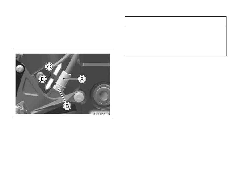
134 MAINTENANCE AND ADJUSTMENT
Adjustment
CAUTION
• To adjust the rear brake light switch,
To avoid damaging the electrical
move the switch up or down by turn-
connections inside the switch,
ing the adjusting nut.
be sure that the switch body
does not turn during adjustment.
A. Rear Brake Light Switch
B. Adjusting Nut
C. Lights sooner
D. Lights later
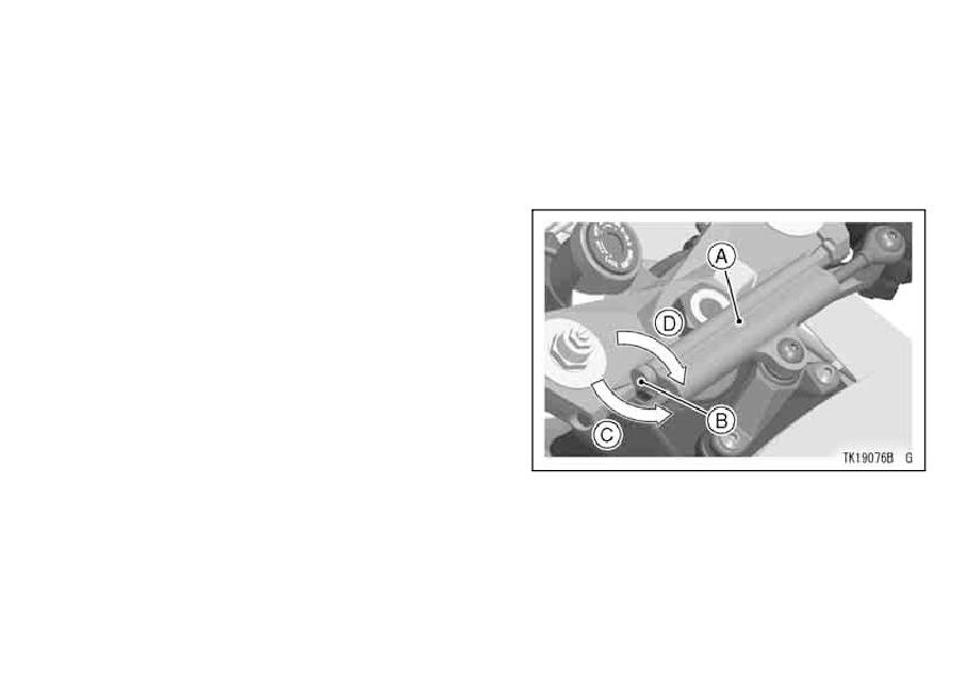
MAINTENANCE AND ADJUSTMENT 135
Steering Damper
Damping Force Adjustment
This motorcycle is equipped with
When adjusting the damping force of
a steering damper unit.
Kawasaki
the steering damper, turn the damp-
recommends that the steering damp-
ing force adjuster clockwise or counter-
ing adjuster is at the standard setting
clockwise as the following figure.
during everyday riding. When adjust-
ing the damping adjuster for use in
a closed course, adjustment should
be done by an authorized Kawasaki
dealer.
The steering operation should be
checked and the steering damper unit
should be inspected for oil leakage
each day before riding, and in accor-
dance with the Periodic Maintenance
Chart.
A. Steering Damper Unit
B. Damping Force Adjuster
C. Softer
D. Harder
136 MAINTENANCE AND ADJUSTMENT
Steering Damping Adjuster Standard
Front Fork
Setting
The front fork operation and oil leak-
18 clicks*
age should be checked in accordance
with the Periodic Maintenance Chart.
* : Fully turned to the softer direction
Front Fork Inspection
• Holding the brake lever, pump the
front fork up and down several times
to inspect smooth stroke.
• Visually inspect the front fork for oil
leakage, scoring or scratches on the
outer surface of the inner tube.
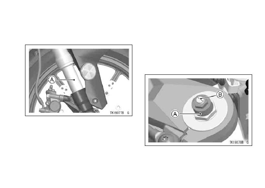
MAINTENANCE AND ADJUSTMENT 137
so that the spring force and damping
• If any doubt about the front fork, it
should be done by an authorized
force can be adjusted for different rid-
Kawasaki dealer.
ing and loading conditions. Weaker
spring force and damping force are
for comfortable riding, but they should
be increased for high speed riding or
riding on rough roads.
A. Inner Tube
On top of each front fork leg are a
spring preload adjuster and a rebound
damping force adjuster, and on the
lower portion of each front fork leg is
A. Spring Preload Adjuster
B. Rebound Damping Force Adjuster
a compression damping force adjuster
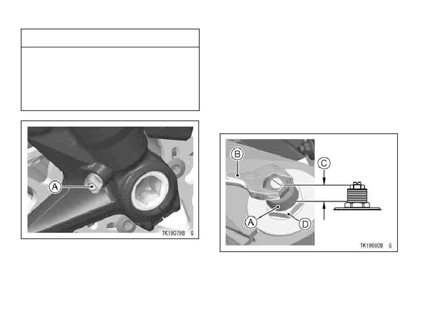
138 MAINTENANCE AND ADJUSTMENT
CAUTION
Spring Preload Adjustment
Do not force to turn the rebound
• Turn the spring preload adjusters into
the nut to increase spring force and
and compression damping force
out to decrease spring force using
adjuster from the fully seated po-
the wrench. The adjusting range is
sition, at the adjusting mecha-
measured from the top of each ad-
nism may be damaged.
juster. Be sure to turn both adjusters
to the same position.
A. Compression Damping Force Adjuster
A. Spring Preload Adjuster
B. Wrench
C. Adjustable Range
D. Nut
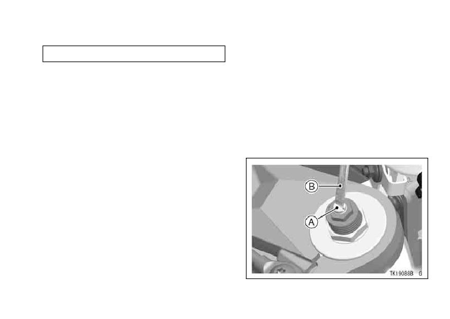
MAINTENANCE AND ADJUSTMENT 139
Adjusting Range
Rebound Damping Force Adjustment
4 ∼ 19 mm (0.2 ∼ 0.7 in.)
• Turn the rebound damping force
adjuster all the way into the spring
preload adjuster with a screwdriver.
This makes the damping force great-
est.
• Turn out the adjuster to decrease
damping force. Be sure to turn both
adjusters by the same number of
turns.
A. Rebound Damping Force Adjuster
B. Screwdriver
140 MAINTENANCE AND ADJUSTMENT
Compression
Damping
Force
The standard setting positions of
Adjustment
the spring preload adjuster, rebound
damping force adjuster and compres-
• Turn the compression damping force
adjuster all the way clockwise with
sion damping force adjuster for an
a screwdriver to make the damping
average-build rider of 68 kg (150 lb)
force greatest.
with no passenger and no accessories
are as follows:
• Turn the adjuster counterclockwise
to decrease damping force. Be sure
to turn both adjusters by the same
Spring Preload
14 mm (0.6 in.)
number of turns.
Adjuster
from top of adjuster
Rebound Damping
10 clicks*
WARNING
Force Adjuster
If both spring preload adjusters
Compression
Damping Force
10 clicks*
and both rebound and compres-
Adjuster
sion damping force adjusters
are not adjusted equally, han-
*: out from the fully seated position
dling may be impaired and haz-
ardous condition may result.
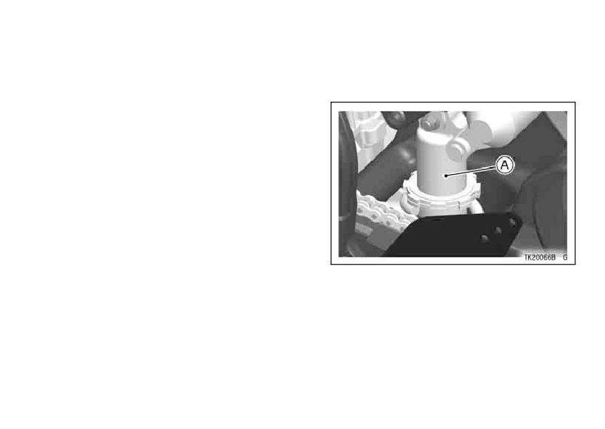
MAINTENANCE AND ADJUSTMENT 141
Rear Shock Absorber
• If any doubt about the rear shock ab-
The rear shock absorber operation
sorber, it should be done by an au-
and oil leakage should be checked in
thorized Kawasaki dealer.
accordance with the Periodic Mainte-
nance Chart.
Rear Shock Absorber Inspection
• Press down on the seat several times
to inspect the stroke.
• Visually inspect the rear shock ab-
sorber for oil leakage.
A. Rear Shock Absorber
The rear shock absorber can be ad-
justed by changing the spring preload
and rebound and compression damp-
ing force for various riding and loading
conditions.
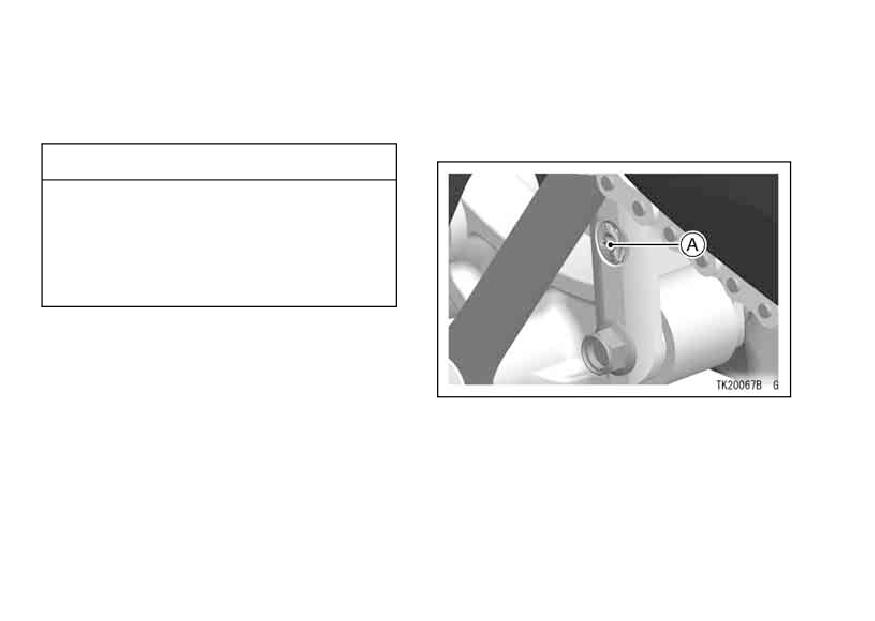
142 MAINTENANCE AND ADJUSTMENT
Before making any adjustments,
Rebound Damping Force Adjustment
however, read the following proce-
The rebound damping force adjuster
dures:
is located at the lower end of the rear
shock absorber.
CAUTION
Do not force to turn the rebound
and compression damping force
adjuster from the fully seated po-
sition or the adjusting mecha-
nism may be damaged.
Spring Preload Adjustment
The spring adjusting nut on the rear
shock absorber can be adjusted.
If the spring action feels too soft or too
A. Rebound Damping Force Adjuster
stiff, have it adjusted by an authorized
• Turn the rebound damping force ad-
Kawasaki dealer.
juster all the way clockwise with a
screwdriver to make the damping
force greatest.
• Turn the adjuster counterclockwise
to decrease damping force.
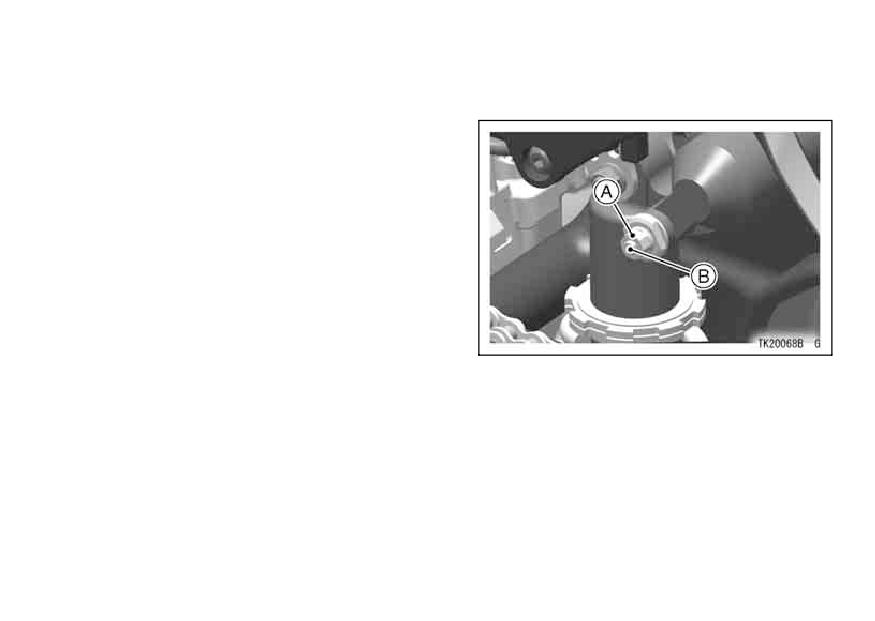
MAINTENANCE AND ADJUSTMENT 143
Compression
Damping
Force
to decrease high speed compression
Adjustment
damping.
The compression damping force ad-
juster is located on the gas reservoir
at the upper end of the rear shock ab-
sorber.
• The compression damping adjuster
has both high and low speed com-
pression damping adjusters.
Low Speed Compression Damping
Adjustment
Turn the low speed compression
adjuster screw clockwise to increase
A. High Speed Adjuster
B. Low Speed Adjuster
low speed damping. Turn the adjuster
screw counterclockwise to decrease
low speed compression damping.
High Speed Compression Damping
Adjustment
Turn the outer screw clockwise to in-
crease high speed compression damp-
ing. Turn the screw counterclockwise
144 MAINTENANCE AND ADJUSTMENT
NOTE
2 turns
Rebound Damping Adjuster
out*
żTurning the high speed adjuster has
the low speed adjuster turning. Al-
2 3/4 turns
Compression
High Speed
though the low speed adjuster turns
out*
Damping
with the high speed adjuster when
2 1/4 turns
Adjuster
Low Speed
turning the high speed adjuster, the
out*
low speed adjuster setting position
dose not change.
*: out from the fully seated position
The standard setting positions of the
WARNING
rebound damping force adjuster and
compression damping force adjuster
This unit contains high pressure
for an average-build rider of 68 kg (150
nitrogen gas. Mishandling can
lb) with no passenger and no acces-
cause explosion.
sories are as follows:
Read service Manual for instruc-
tions.
Do not incinerate, puncture or
open.
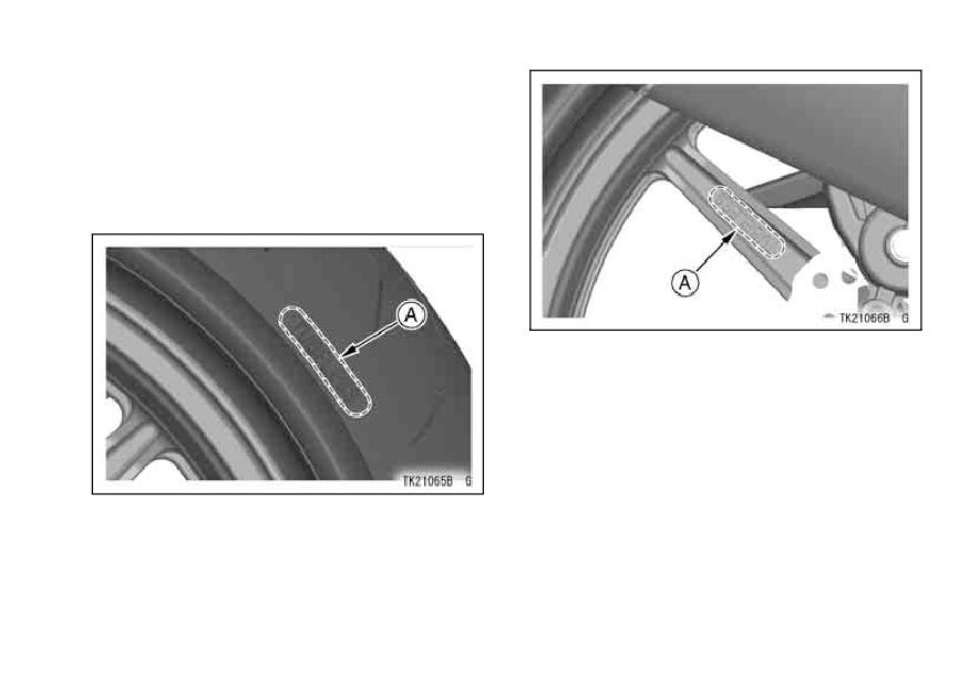
MAINTENANCE AND ADJUSTMENT 145
Wheels
Tubeless tires are installed on the
wheels of this motorcycle. The indica-
tions of TUBELESS on the tire side wall
and the rim show that the tire and rim
are specially designed for tubeless use.
A. TUBELESS Mark
A. TUBELESS Mark
146 MAINTENANCE AND ADJUSTMENT
The tire and rim form a leakproof unit
Tires -
by making airtight contacts at the tire
Payload and Tire Pressure
chamfers and the rim flanges instead
Failure to maintain proper inflation
of using an inner tube.
pressures or observe payload limits for
your tires may adversely affect han-
WARNING
dling and performance of your motorcy-
The tires, rims, and air valves
cle and can result in loss of control. The
on this motorcycle are designed
maximum recommended load in addi-
only for tubeless type wheels.
tion to vehicle weight is 180 kg (397 lb),
The recommended standard
including rider, passenger, baggage,
tires, rims, and air valves must
and accessories.
be used for replacement.
• Remove the air valve cap.
Do not install tube-type tires on
• Check the tire pressure often, using
tubeless rims. The beads may
an accurate gauge.
not seat properly on the rim
• Make sure to install the air valve cap
causing tire deflation.
securely.
Do not install a tube inside a
tubeless tire. Excessive heat
NOTE
build-up may damage the tube
żMeasure the tire pressure when the
causing tire deflation.
tires are cold (that is, when the mo-
torcycle has not been ridden more
than a mile during the past 3 hours).
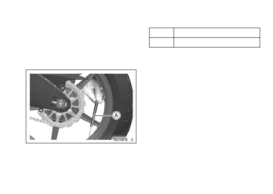
MAINTENANCE AND ADJUSTMENT 147
żTire pressure is affected by changes
Tire Air Pressure (when cold)
in ambient temperature and altitude,
Front
250 kPa (2.50 kgf/cm², 36 psi)
and so the tire pressure should be
Rear
290 kPa (2.90 kgf/cm², 42 psi)
checked and adjusted when your rid-
ing involves wide variations in tem-
perature or altitude.
Tire Wear, Damage
As the tire tread wears down, the tire
becomes more susceptible to puncture
and failure. An accepted estimate is
that 90% of all tire failures occur during
the last 10% of tread life (90% worn).
So it is false economy and unsafe to
use the tires until they are bald.
A. Tire Pressure Gauge
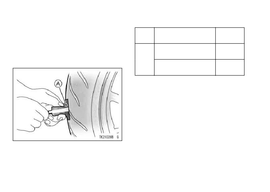
148 MAINTENANCE AND ADJUSTMENT
Minimum Tread Depth
• In accordance with the Periodic
Maintenance Chart, measure the
1 mm
Front
-
depth of the tread with a depth
(0.04 in.)
gauge, and replace any tire that
Under 130 km/h
2 mm
has worn down to the minimum al-
(80 mph)
(0.08 in.)
lowable tread depth.
Rear
Over 130 km/h
3 mm
(80 mph)
(0.12 in.)
• Visually inspect the tire for cracks
and cuts, replacing the tire in case of
bad damage. Swelling or high spots
indicate internal damage, requiring
tire replacement.
•Removeeianyimbeddedstonesaor
NOTE
A. Tire Depth Gauge
żHave the wheel balance inspected
whenever a new tire is installed.
MAINTENANCE AND ADJUSTMENT 149
WARNING
Standard Tire (Tubeless)
Size: 120/70ZR17 M/C (58 W)
To ensure safe handling and
stability, use only the recom-
•PIRELLI “DIABLO CORSA III N”
Front
mended standard tires for re-
placement, inflated to the stan-
•BRIDGESTONE
“BATTLAX BT016F J”
dard pressure.
Size: 190/55ZR17 M/C (75 W)
Tires that have been punctured
and repaired do not have the
•PIRELLI “DIABLO CORSA III”
Rear
same capabilities as undam-
aged tires. Do not exceed 100
•BRIDGESTONE
“BATTLAX BT016R J”
km/h (60 mph) within 24 hours
after repair, and 180 km/h (110
mph) at any time after that.
WARNING
Use the same manufacturer’s
NOTE
tires on both front and rear
wheels.
żMost countries may have their own
regulations requiring a minimum tire
tread depth; be sure to follow them.
żWhen operating on public roadways,
keep maximum speed under traffic
law limits.
150 MAINTENANCE AND ADJUSTMENT
WARNING
Battery
The battery installed in this motorcy-
New tires are slippery and may
cle is a sealed type, so it is not nec-
cause loss of control and injury.
essary to check the battery electrolyte
A break-in period of 160 km (100
level or add distilled water.
miles) is necessary to estab-
The sealing strip should not be pulled
lish normal tire traction. During
off once the specified electrolyte has
break-in, avoid sudden and max-
been installed in the battery for initial
imum braking and acceleration,
service.
and hard cornering.
However, in order to maximize bat-
tery life and ensure that it will provide
the power needed to start the motor-
cycle you must properly maintain the
battery’s charge. When used regularly,
the charging system in the motorcycle
helps keep the battery fully charged. If
your motorcycle is only used occasion-
ally or for short periods of time, the bat-
tery is more likely to discharge.
Due to their internal composition,
batteries continually self discharge.
The discharge rate depends on the
MAINTENANCE AND ADJUSTMENT 151
type of battery and ambient temper-
Self-discharge
ature. As temperatures rise, so does
Approx. Number of Days
the discharge rate. Every 15 °C (27 °F)
From 100% Charged to
doubles the rate.
100% discharged
Electrical accessories, such as digi-
Temperature
Lead
Lead
tal clocks and computer memory, also
-Antimony
-Calcium
draw current from the battery even
when the key is switched off. Combine
Battery
Battery
such “key-off” draws with hot temper-
40 °C
100 Days
300 Days
ature, and a battery can go from fully
(104 °F)
charged to completely discharged in a
25 °C
matter of days.
200 Days
600 Days
(77 °F)
0 °C (32 °F)
550 Days
950 Days
152 MAINTENANCE AND ADJUSTMENT
Current Drain
Battery Sulfation
A common cause of battery failure is
Days form
Days form
sulfation.
100%
100%
Discharging
Sulfation occurs when the battery is
charged to
charged to
Ampere
50%
100%
left in a discharged condition for an ex-
Discharged
Discharged
tended time. Sulfate is a normal by
product of the chemical reactions within
7 mA
60 Days
119 Days
a battery. But when continuous dis-
10 mA
42 Days
83 Days
charge allows the sulfate to crystallize
15 mA
28 Days
56 Days
in the cells, the battery plates become
permanently damaged and will not hold
20 mA
21 Days
42 Days
a charge. Battery failure due to sulfa-
30 mA
14 Days
28 Days
tion is not warrantable.
In extremely cold weather the fluid in
an inadequately charged battery can
easily freeze, which can crack the case
and buckle the plates. A fully charged
battery can withstand sub-freezing
temperatures with no damage.
MAINTENANCE AND ADJUSTMENT 153
Battery Maintenance
Kawasaki-recommended chargers
It is the owner’s responsibility to keep
are:
the battery fully charged. Failure to do
OptiMate ǿǿǿ
so can lead to battery failure and leave
Yuasa 1.5 Amp Automatic charger
you stranded.
Battery Mate 150-9
If you are riding your vehicle infre-
If the above chargers are not avail-
quently, inspect the battery voltage
able, use equivalent one.
weekly using a voltmeter. If it drops
For more details, ask your Kawasaki
below 12.8 volts, the battery should be
dealer.
charged using an appropriate charger
(check with your Kawasaki dealer).
Battery Charging
If you will not be using the motorcy-
• Remove the battery from the motor-
cle for longer than two weeks, the
cycle (see Battery Removal).
battery should be charged using an
• Attach the leads from the charger
appropriate charger. Do not use an au-
and charge the battery at a rate that
tomotive-type quick charger that may
is 1/10th of the battery capacity. For
overcharge the battery and damage it.
example, the charging rate for a 10
Ah battery would be 1.0 ampere.
• The charger will keep the battery fully
charged until you are ready to re-
install the battery in the motorcycle
(see Battery Installation).
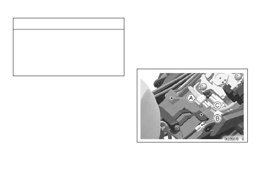
154 MAINTENANCE AND ADJUSTMENT
CAUTION
Battery Removal
Never remove the sealing strip,
• Remove the rider’s seat.
or the battery can be damaged.
• Unhook the rubber band.
Do not install a conventional
• Disconnect the wire from the battery,
first from the (-) terminal and then the
battery in this motorcycle, or the
(+) terminal.
electrical system cannot work
properly.
NOTE
żIf you charge the sealed battery,
never fail to observe the instructions
shown in the label on the battery.
A. (+) Terminal
B. (-) Terminal
C. Rubber Band
MAINTENANCE AND ADJUSTMENT 155
CAUTION
• Take the battery out of the case.
• Clean the battery using a solution of
Installing the (-) wire to the (+)
baking soda and water. Be sure that
terminal of the battery or the (+)
the wire connections are clean.
wire to the (-) terminal of the bat-
tery can seriously damaged the
Battery Installation
electrical system.
• Place the battery in the battery case.
• Connect the red capped wire to the
(+) terminal, and then connect the
• Put a light coat of grease on the ter-
minals to prevent corrosion.
black capped wire to the (-) terminal.
• Cover the terminals with its protec-
tive cap.
NOTE
• Reinstall the parts removed.
żInstall the battery in the reverse order
of the Battery Removal.
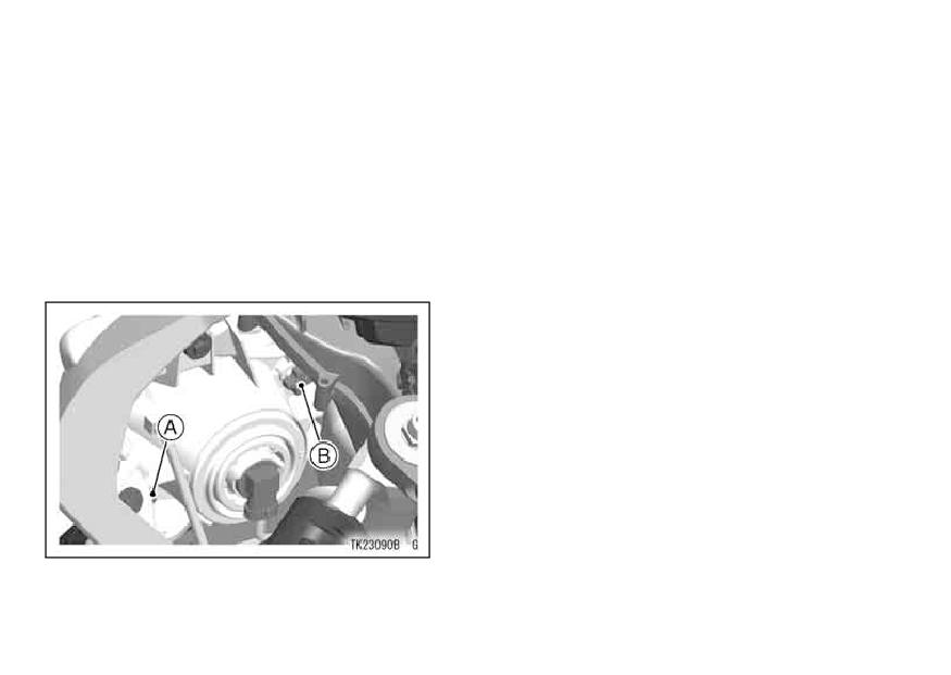
156 MAINTENANCE AND ADJUSTMENT
Headlight Beam
Vertical Adjustment
The headlight beam is adjustable ver-
Horizontal Adjustment
tically. If adjusted too low, neither low
The headlight beam is adjustable
nor high beam will illuminate the road
horizontally. If not properly adjusted
far enough ahead. If adjusted too high,
horizontally, the beam will point to one
the high beam will fail to illuminate the
side rather than straight ahead.
road close ahead, and the low beam
• Turn the horizontal adjuster in or out
will blind oncoming drivers.
until the beam points straight ahead.
• Turn the vertical adjuster in or out to
adjust the headlight vertically.
NOTE
ż
On high beam, the brightest point
should be slightly below horizontal
with the motorcycle on its wheels and
the rider seated. Adjust the headlight
to the proper angle according to local
regulations.
A. Horizontal Adjuster
B. Vertical Adjuster
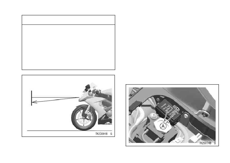
MAINTENANCE AND ADJUSTMENT 157
CAUTION
Fuses
Fuses are arranged in the fuse box
When handling the quartz
located under the seat. The main fuse
-halogen bulbs, never touch the
is located under the fuel tank. If a fuse
glass portion with bare hands.
fails during operation, inspect the elec-
Always use a clean cloth. Oil
trical system to determine the cause,
contamination from hands or
and then replace it with a new fuse of
dirty rags can reduce bulb life or
proper amperage.
cause the bulb to explode.
The main fuse removal should be
done by an authorized Kawasaki
dealer.
A. Fuse Box
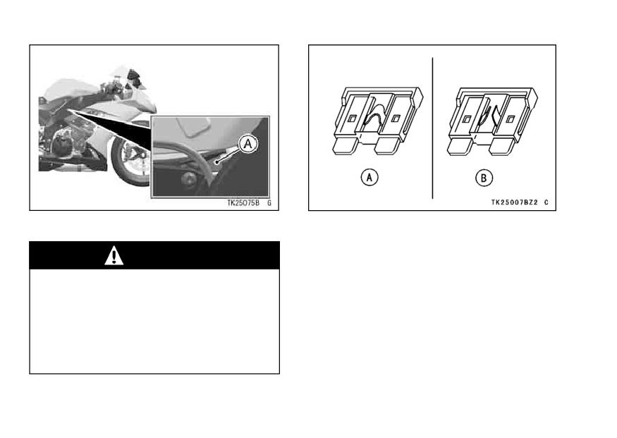
158 MAINTENANCE AND ADJUSTMENT
A. Main Fuse
A. Normal
B. Failed
WARNING
Do not use any substitute for the
standard fuse.
Replace the blown fuse with a
new one of the correct capacity,
as specified on the fuse box and
main fuse.
MAINTENANCE AND ADJUSTMENT 159
Cleaning Your Motorcycle
• Gasoline, brake fluid, and coolant
will damage the finish of painted and
General Precautions
plastic surfaces: wash them off im-
Frequent and proper care of your
mediately.
Kawasaki motorcycle will enhance
its appearance, optimize overall per-
• Avoid wire brushes, steel wool, and
all other abrasive pads or brushes.
formance, and extend its useful life.
Covering your motorcycle with a high
• Use care when washing the wind-
shield, headlight cover, and other
quality, breathable motorcycle cover
plastic parts as they can easily be
will help protect its finish from harmful
scratched.
UV rays, pollutants, and reduce the
amount of dust reaching its surfaces.
• Avoid using pressure washers; wa-
ter can penetrate seals and electrical
• Be sure the engine and exhaust are
components and damage your mo-
cool before washing.
torcycle.
• Avoid applying degreaser to seals,
brake pads, and tires.
• Avoid spraying water in delicate
areas such as in air intakes, fuel
• Avoid all harsh chemicals, solvents,
system, brake components, electri-
detergents, and household cleaning
cal components, muffler outlets, and
products such as ammonia-based
fuel tank openings.
window cleaners.
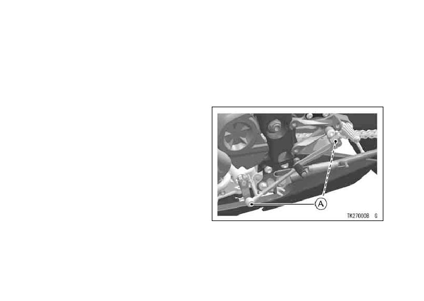
160 MAINTENANCE AND ADJUSTMENT
Washing Your Motorcycle
• After cleaning your motorcycle,
check the rubber boot covering the
• Rinse your bike with cold water from
a garden hose to remove any loose
shift pedal ball joint for correct instal-
dirt.
lation. Be sure the sealing lip of the
rubber boot fits into the groove of the
• Mix a mild neutral detergent (de-
signed for motorcycles or automo-
ball joint.
biles) and water in bucket.
Use
a soft cloth or sponge to wash your
motorcycle. If needed, use a mild de-
greaser to remove any oil or grease
build up.
• After washing, rinse your motorcy-
cle thoroughly with clean water to re-
move any residue (residue from the
detergent can damage parts of your
motorcycle).
• Use a soft cloth to dry your motorcy-
cle. As you dry, inspect your motor-
A. Boots
cycle for chips and scratches. Do not
let the water air dry as this can dam-
age the painted surfaces.
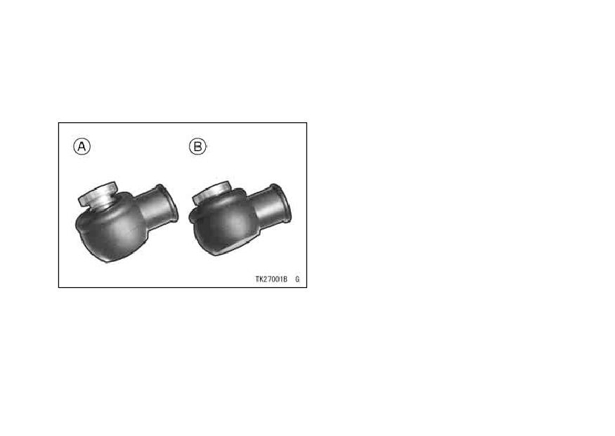
MAINTENANCE AND ADJUSTMENT 161
• If the boot is damaged, replace it with
• Start the engine and let it idle for sev-
a new one. If the boot is not po-
eral minutes. The heat from the en-
sitioned in the groove correctly, re-
gine will help dry moist areas.
place it in the correct position.
• Carefully ride your motorcycle at a
slow speed and apply the brakes
several times. This helps dry the
brakes and restores them to normal
operating performance.
te the drive chain to prevent
•Lubrica
A. Wrongly set lip not in the correct position
B. Lip set correctly in the groove
162 MAINTENANCE AND ADJUSTMENT
NOTE
Semi-Gloss Finish
Semi-Gloss Finish is used for this
żAfter riding in an area where the
motorcycle.
roads are salted or near the ocean,
immediately wash your motorcycle
• When washing the motorcycle, al-
ways use a mild neutral detergent
with cold water. Do not use warm
and water.
water as it accelerates the chemical
reaction of the salt. After drying,
• The semi-gloss finish effect may be
lost when it is excessively rubbed.
apply a corrosion protection spray
on all metal and chrome surfaces to
• If any doubt, consult an authorized
Kawasaki dealer.
prevent corrosion.
żCondensation may form on the inside
Windshield and Other Plastic Parts
of the headlight lens after riding in the
After washing use a soft cloth to
rain, washing the motorcycle or hu-
gently dry plastic parts. When dry,
mid weather. To remove the mois-
treat the windshield, headlight lens,
ture, start the engine and turn on the
and other nonpainted plastic parts with
headlight. Gradually the condensa-
an approved plastic cleaner/polisher
tion on the inside of the lens will clear
product.
off.
MAINTENANCE AND ADJUSTMENT 163
CAUTION
Chrome and Aluminum
Chrome and uncoated aluminum
Plastic parts may deteriorate
parts can be treated with a chrome/alu-
and break if they come in con-
minum polish.
Coated aluminum
tact with chemical substances
should be washed with a mild neu-
or household cleaning products
tral detergent and finished with a spray
such as gasoline, brake fluid,
polish. Aluminum wheels, both painted
window cleaners, thread-locking
and unpainted can be cleaned with
agents, or other harsh chemi-
special non-acid based wheel spray
cals. If a plastic part comes in
cleaners.
contact with any harsh chemical
substance, wash it off immedi-
Leather, Vinyl, and Rubber
ately with water and a mild neu-
If your motorcycle has leather ac-
tral detergent, and then inspect
cessories, special care must be taken.
for damage. Avoid using abra-
Use a leather cleaner/treatment to
sive pads or brushes to clean
clean and care for leather accessories.
plastic parts, as they will dam-
Washing leather parts with detergent
age the part’s finish.
and water will damage them, shorten-
ing their life.
Vinyl parts should be washed with the
rest of the motorcycle, then treated with
a vinyl treatment.
164 MAINTENANCE AND ADJUSTMENT
The sidewalls of tires and other rub-
WARNING
ber components should be treated with
Special care must be taken not to
a rubber protectant to help prolong their
get any rubber protectant on the
useful life.
tire’s tread surface when treat-
ing tires. This may decrease the
tire’s ability to maintain contact
with the road surface causing
the rider to lose control.
STORAGE 165
STORAGE
Preparation for Storage -
• Clean the entire vehicle thoroughly.
• Run the engine for about five minutes to warm the oil, shut it off, and drain the
engine oil.
WARNING
Motorcycle oil is a toxic substance. Dispose of used oil properly. Con-
tact your local authorities for approved disposal methods or possible re-
cycling.
• Put in fresh engine oil.
• Empty the fuel from the fuel tank by the pump or siphon.
166 STORAGE
WARNING
Gasoline is extremely flammable and can be explosive under certain con-
ditions. Turn the ignition key to “OFF”. Do not smoke. Make sure the
area is well ventilated and free from any source of flame or sparks; this
includes any appliance with a pilot light.
Gasoline is a toxic substance. Dispose of gasoline properly. Contact your
local authorities for approved disposal methods.
• Empty the fuel system by running the engine at idle speed until the engine stalls
(If left in for a long time, the fuel will break down and could clog the fuel system).
• Reduce tire pressure by about 20%.
• Set the motorcycle on a box or stand so that both wheels are raised off the ground.
(If this cannot be done, put boards under the front and rear wheels to keep damp-
ness away from the tire rubber.)
• Spray oil on all unpainted metal surfaces to prevent rusting. Avoid getting oil on
rubber parts or in the brakes.
• Lubricate the drive chain and all the cables.
• Remove the battery, and store it where it will not be exposed to direct sunlight,
moisture, or freezing temperatures. During storage it should be given a slow
charge (one ampere or less) about once a month. Keep the battery well charged
especially during cold weather.
• Tie plastic bags over the mufflers to prevent moisture from entering.
STORAGE 167
• Put a cover over the motorcycle to keep dust and dirt from collecting on it.
Preparation after Storage -
• Remove the plastic bags from the mufflers.
• Install the battery in the motorcycle and charge the battery if necessary.
• Fill the fuel tank with fuel.
• Check all the points listed in the Daily Safety Checks section.
• Lubricate the pivots, bolts, and nuts.
168 ENVIRONMENTAL PROTECTION
ENVIRONMENTAL PROTECTION
To protect our environment, properly discard used batteries, tires, engine oil, or
other vehicle components that you might dispose of in the future. Consult your
authorized Kawasaki dealer or local environmental waste agency for their proper
disposal procedures.
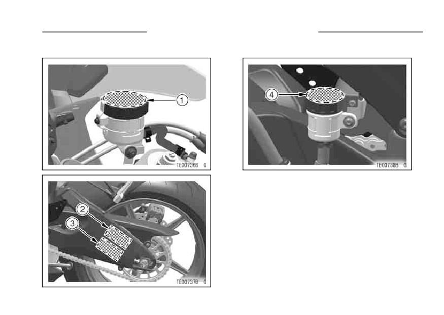
LOCATION OF LABELS 169
LOCATION OF LABELS
1. Brake Fluid (Front)
2. Important Drive Chain Information
3. Tire and Load Data
4. Brake Fluid (Rear)
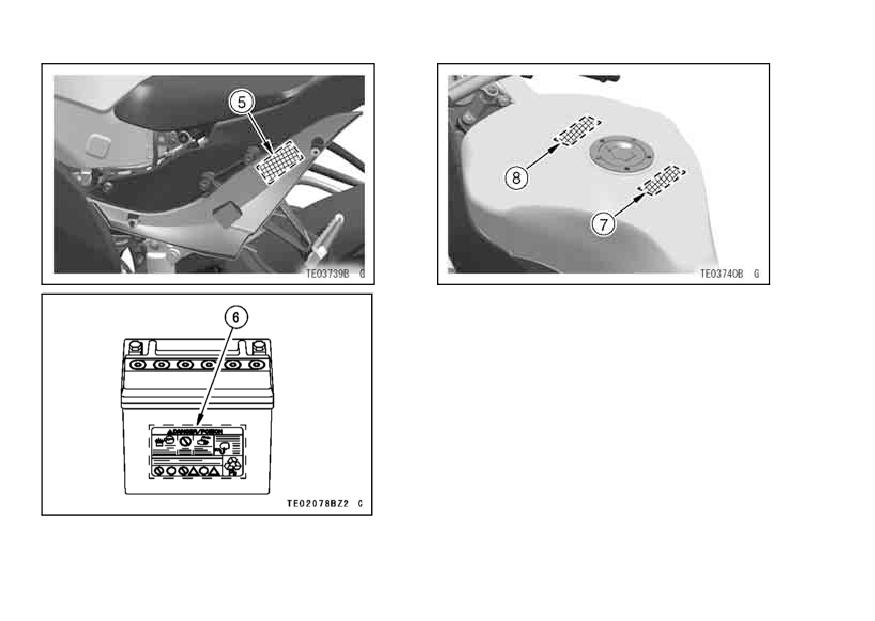
170 LOCATION OF LABELS
5. Daily Safety Checks
6. Battery Poison/Danger
*7. Unleaded Gasoline
8. Fuel Caution
*: Expect for Australia model